X4电路图.pdf - 第246页
4 - 9 0304622 5-010 101 TD1 Main di stributo r , SIPLACE X-Se ries Copy rig ht Re se rv ed Rep la ce me nt fo r Modific ation / EC O No. Date K I H G F E D C B A K I H G F E D C B A 15 14 13 12 11 10 9 8 7 6 5 4 3 2 1 16…
4 - 8
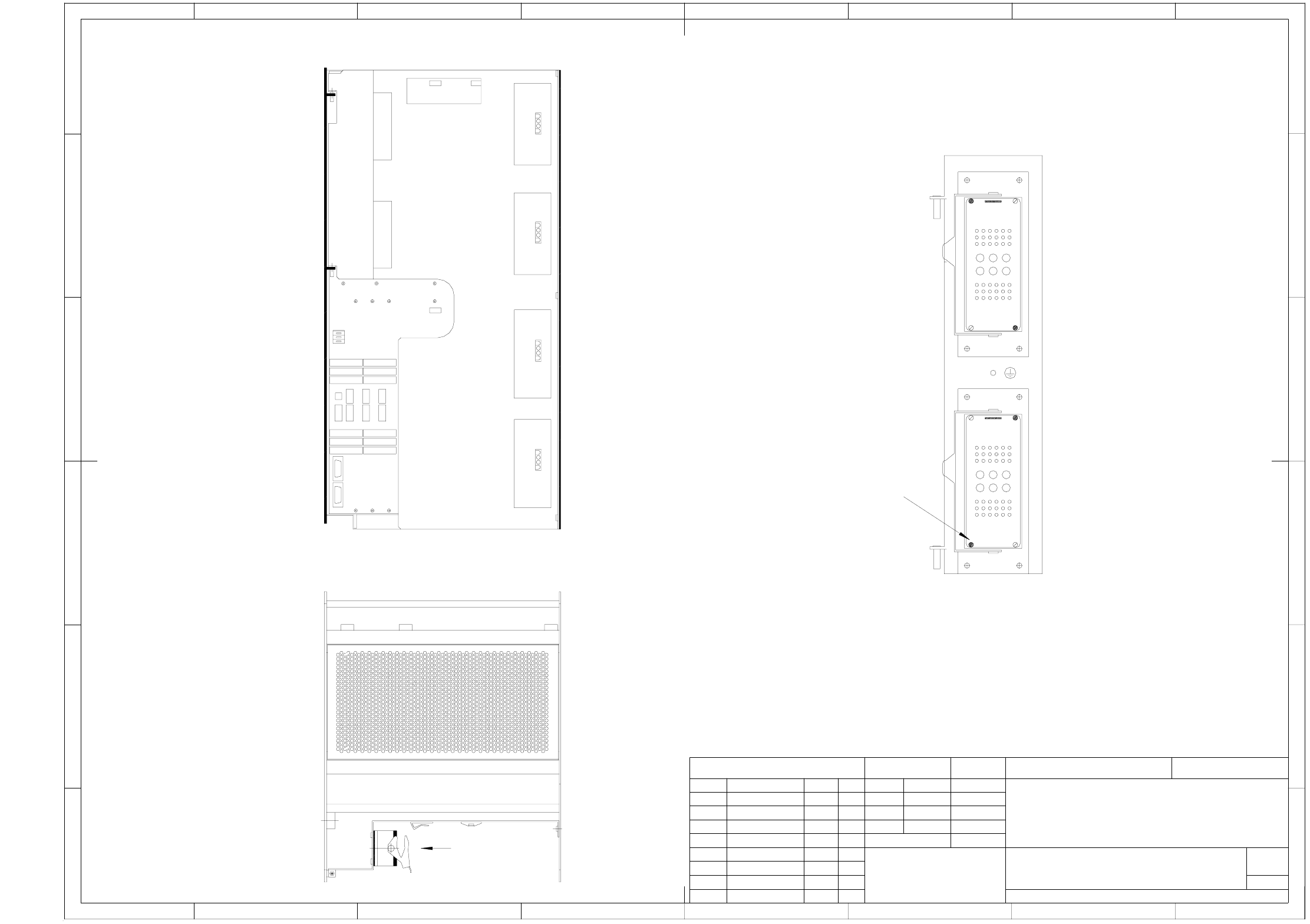
03042047-010101TD3 A364 axis unit (sh. 3 of 3)
oben
top
front
Achseinschub: Draufsicht
Axis unit: topview
Achseinschub: Rückansicht
Axis unit: rear view
X22 X21
X22
oben
top
X21
Ansicht A
View A
Ansicht A
View A
23
11 16
28
46
3429
41
123
456
23
11 16
28
46
3429
41
123
456
Kodierbolzen (4x)
Coding pin (4x)
Weitergabe sowie Vervielfältigung dieser Unterlage, Verwer-
tung und Mitteilung ihres Inhalts nicht gestattet, soweit nicht
ausdrücklich zugestanden. Zuwiderhandlungen verpflichten zu
Schadenersatz. Alle Rechte für den Fall der Patenterteilung
oder GM-Eintragung vorbehalten.
Copying of this document, and giving it to others and the use
or communication of the contents thereof, are forbidden with-
out express authority. Offenders are liable to the payment of
damages. All rights are reserved in the event of the grant of
a patent or the registration of a utility model or design.
56784321
B
A
C
D
E
F
B
A
C
D
E
F
5674321 8
SIPLACE X-Series
Achseinschub A364
A364 axis unit
Scale
Document - No. / Unterlagen - Nr. (FS RS US UA SP F)
03042047-010101TD3
Replacement for
Request No.
Change
Modification / ECO No.
Date
25.10.05
27.06.2005
Copyright Reserved
Siemens AG
Name
Standards
Checked
Drawn
Date
Pommer H.
Name
1:2
Format
Sheet
of
3
3
A3
vorne
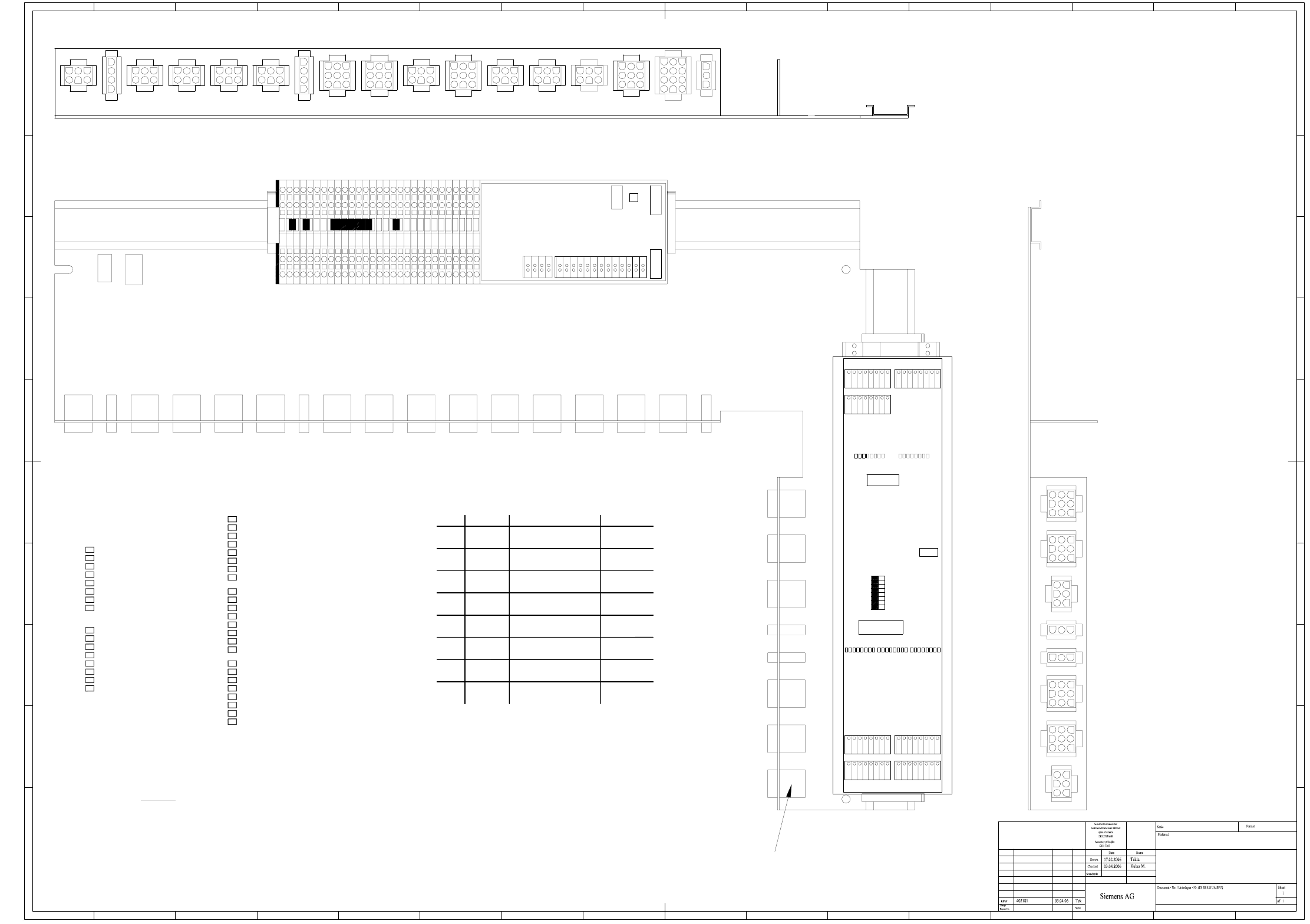
4 - 9
03046225-010101TD1 Main distributor, SIPLACE X-Series
Copyright Reserved
Replacement for
Modification / ECO No. Date
K
I
H
G
F
E
D
C
B
A
K
I
H
G
F
E
D
C
B
A
151413121110987654321
16151413121110987654321
Weitergabe sowie Vervielfältigung dieser Unterlage, Verwer-
tung und Mitteilung ihres Inhalts nicht gestattet, soweit nicht
ausdrücklich zugestanden. Zuwiderhandlungen verpflichten zu
Schadenersatz. Alle Rechte für den Fall der Patenterteilung
oder GM-Eintragung vorbehalten.
Copying of this document, and giving it to others and the use
or communication of the contents thereof, are forbidden with-
out express authority. Offenders are liable to the payment of
damages. All rights are reserved in the event of the grant of
a patent or the registration of a uti lity model or design.
16
A&D
03046225-010101TD1
Hauptverteiler
Main distributor
A1
A3 (qc)
X1qc
123
567
4
8
131211123
14 15 16
10987654
17 18
X6qc
X4qc
X5qc
X3qc
2625242322212019
X2qc
DI23
DI16
DI15
DI8
DI7
DI0
A1 (qb)
S1.1
OFF="0"
ON="1"
10
S1.8
S1
X10qb
X1qb
X2qb
DO9
DO8
DO15
DO14
DO13
DO12
DO11
GND
GND
GND
P24
P24
P24
DO7
DO6
DO5
DO4
DO3
DO2
DO1
DO0
87654321
87654321
X9qb
GND
P24
87654321
X8qb X7qb
DO10
DI7
DI6
DI5
DI4
DI3
DI2
DI1
DI0
DI15
DI14
DI13
DI12
DI11
DI10
DI9
DI8
DI23
DI22
DI21
DI20
DI19
DI18
DI17
X3qbX4qb
87654321 87654321
X5qb
87654321
DI16
X6qb
87654321
DI7_5V
DI6_5V
DI5_5V
DI4_5V
EGND
EGND
GND
VCC
LEDs
LEDs
DO15
DO0
DO0
DO8
K2
Steckerbeschriftung auf der Kante (Schriftgröße: 4mm)
Connector label on the edge (font size: 4mm)
X15qa
X15qa
X1qa
X22qa
X19qa
X20qa
X21qa
X18qa
X24qa
X23qa
X17qa
X16qa X14qa X13qa X12qa X11qa X10qa X73qa X71qaX72qaX9qa X6qa X5qa X4qa X3qa X2qa X74qa
26
25
24
23
22
21
20
19
18
17
16
15
14
13
12
11
10
9
8
7
6
5
4
3
2
B
A
X16qa X14qa X13qa X12qa X11qa X10qa X73qa X71qaX72qaX9qa X6qa X5qa X4qa X3qa X2qa X74qa
X22qa
X19qa
X20qa
X21qa
X18qa
X24qa
X23qa
X17qa
1
27
28
29
Fit the following labels:
* Please note
A: identification label
B: inspection label
DI16 - S_Emerg.StopCircuit2OkDO12 - Ctrl_GreenIndicator1
DI19 - S_HoodPCB-Output
DI17 - S_Hood2
DI18 - S_CompTable2
DI21 - S_Hood3
DI22 - S_CompTable3
DI20 - S_Emerg.StopButtonPCB-Output
DO14 - Ctrl_FaultIndicator2
DO13 - Ctrl_FaultIndicator1
DO15 - Ctrl_GreenIndicator2
DI23 -
LEDs on the CAN input / output module
DI9 - S_Ready
DI15 - S_PressureSensor RV/TWIN
DI13 - S_ControlOn
DI10 - S_VacuumOK
DI11 - S_GantryCrash1
DI3 - S_Flap
DI0 - Emerg.StopCircuit1Ok
DO3 - Ctrl_Pressure RV/TWIN
DO4 - Ctrl_ComponentCounter
DO1 - Software_CtrlOn
DO6 -
DO10 -
DO11 -
DO9 -
DO7 -
DO8 -
DO5 -
DO0 -
DO2 -
DI14 -
DI12 -
DI6 -
DI8 -
DI7 -
DI5 -
DI4 -
DI1 -
DI2 -
S1.6 1-Wire ON: 1-Wire MA
ON
OFF:
ON: not used
OFF: not used
ON: not used
OFF: not used
not used
Terminating
resistor
S1.8
S1.7
1-Wire PC
OFF
OFF
S1 switch status on the CAN input/output module
ON: HF, HF/3
Switch status
OFF: D3/X-series
Coding
ON: Slio emulation
OFF: CAN I/O module
ON: Sub Distributor
OFF: Main Distributor
ON: not used
OFF: not used
OFF:
ON: 500k
OFF: 1000k
not used
Location
Baud rate
gateway
S1.5
S1.3
S1.4
Platform
Gateway
Function
S1.2
S1.1
Switch
ON:
OFF
OFF
OFF
Gateway on
Gateway off
OFF
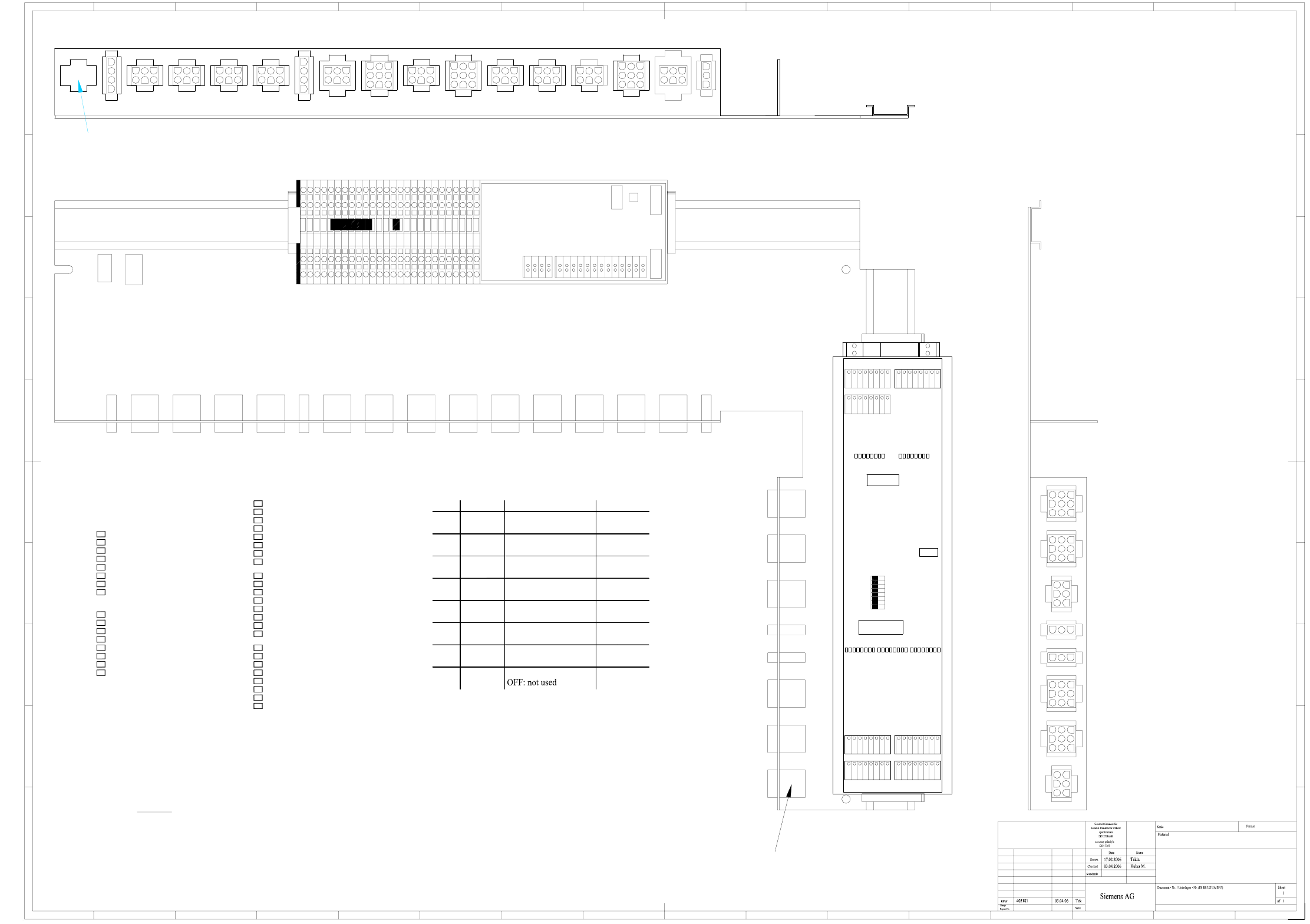
4 - 10
03046226-010101TD1 Sub-distributor, SIPLACE X-Series
K1
Copyright Reserved
Replacement for
Modification / ECO No. Date
K
I
H
G
F
E
D
C
B
A
K
I
H
G
F
E
D
C
B
A
151413121110987654321
16151413121110987654321
Weitergabe sowie Vervielfältigung dieser Unterlage, Verwer-
tung und Mitteilung ihres Inhalts nicht gestattet, soweit nicht
ausdrücklich zugestanden. Zuwiderhandlungen verpflichten zu
Schadenersatz. Alle Rechte für den Fall der Patenterteilung
oder GM-Eintragung vorbehalten.
Copying of this document, and giving it to others and the use
or communication of the contents thereof, are forbidden with-
out express authority. Offenders are liable to the payment of
damages. All rights are reserved in the event of the grant of
a patent or the registration of a uti lity model or design.
16
A&D
03046226-010101TD1
Unterverteiler
Sub-distributor
A1
A3 (rc)
X1rc
123
567
4
8
131211123
14 15 16
10987654
17 18
X6rc
X4rc
X5rc
X3rc
2625242322212019
X2rc
A1 (rb)
DO8
DO0
DO0
DO15
LEDs
LEDs
DI0
DI7
DI8
DI15
DI16
DI23
VCC
GND
EGND
EGND
DI4_5V
DI5_5V
DI6_5V
DI7_5V
12345678
X6rb
DI16
12345678
X5rb
1234567812345678
X4rb X3rb
DI17
DI18
DI19
DI20
DI21
DI22
DI23
DI8
DI9
DI10
DI11
DI12
DI13
DI14
DI15
DI0
DI1
DI2
DI3
DI4
DI5
DI6
DI7
DO10
X7rbX8rb
12345678
P24
GND
X9rb
12345678
12345678
DO0
DO1
DO2
DO3
DO4
DO5
DO6
DO7
P24
P24
P24
GND
GND
GND
DO11
DO12
DO13
DO14
DO15
DO8
DO9
X2rb
X1rb
X10rb
S1
S1.8
01
ON="1"
OFF="0"
S1.1
X2ra
Steckerbeschriftung auf der Kante (Schriftgröße: 4mm)
Connector label on the edge (font size: 4mm)
X1ra
26
25
24
23
22
21
20
19
18
17
16
15
14
13
12
11
10
9
8
7
6
5
4
3
2
B
A
1
Fit the following labels:
* Please note
A: identification label
B: inspection label
reserviert für Option Vakuumpumpe
reserved for option vacuum pump
X10ra
X10ra
X22ra
X19ra
X20ra
X21ra
X18ra
X24ra
X23ra
X17ra
X14ra X13ra X12ra X11ra X73ra X71raX72ra X6ra X5ra X4ra X3ra X74ra
X14ra X13ra X12ra X11ra X73ra X71raX72ra X6ra X5ra X4ra X3ra X74ra
X22ra
X19ra
X20ra
X21ra
X18ra
X24ra
X23ra
X17ra
X15ra
X15ra X9ra
X9ra
X2ra
DO3 -
DO6 - Ctrl_vacuum pump On
DO0 -
DO1 -
DO2 -
DO4 -
DO5 - Ctrl_compr. air main valve
DO7 -
DO14 -
DO8 -
DO9 -
DO10 -
DO11 -
DO12 -
DO13 -
DO15 -
DI16 -
ON
OFF: D3/X-series
OFF
OFF
ON
OFF
OFF
OFF
Switch status
ON: HF, HF/3
S1 switch status on the CAN input/output module
DI19 - S_HoodPCB-Input
DI17 - S_Hood1
DI18 - S_CompTable1
DI21 - S_Hood4
DI22 - S_CompTable4
DI20 - S_Emerg.StopButtonPCB-Input
ON: not used
OFF: not used
ON: not used
OFF:
resistor
Terminating
not used
S1.8
S1.7
1-Wire PC
OFF: 1000k
ON: 500k
ON: 1-Wire MA
OFF: not used
ON: not used
OFF: Main Distributor
ON: Sub Distributor
OFF: CAN I/O module
ON: Slio emulation
Coding
OFF:
ON:
FunctionSwitch
Gateway
gateway
Baud rate
Location
1-Wire
not used
Platform
S1.6
S1.5
S1.4
S1.2
S1.3
S1.1
Gateway off
Gateway on
DI23 -
LEDs on the CAN input / output module
DI9 - S_StopButton
DI15 - S_Emerg.StopButtonMTC
DI13 - S_ControlOn
DI11 - S_gantryCrash 2
DI8 - S_StartButton
DI6 - S_vacuum pump On
DI5 - S_PressureSensor
DI0 - Emerg.StopCircuit1Ok
DI14 -
DI10 -
DI12 -
DI7 -
DI4 -
DI3 -
DI1 -
DI2 -