X4电路图.pdf - 第254页
4 - 17 0304800 4-010 101GD4 Label , A364 axis uni t, 4- gantry machine (sh. 2 of 3) 030480 04-0 10101 GD4 3 07.03.2 006 Tekin Pommer Schild Ax is Unit A36 4 4-Port al- Maschin e Label axis u nit A364 4 gantr y m ac hine …
4 - 16
03048004-010101GD4 Label, A364 axis unit, 4-gantry machine (sh. 1 of 3)
03048004-010101GD4
3
07.03.2006
Tekin
Pommer
Schild Axis Unit A364 4-Portal-Maschine
Label axis unit A364 4 gantry machine
SIPLACE X4
Date
Drawn
Checked
StandardsNameModification
Sheet
of
21 6543
A
B
C
D
Date
Designer 9
21 6543
A4
Document No. / Dokumentennummer:
Item name / Benennung
Copyright reserved
Siemens AG
A&D
Stat.
W
e
i
t
e
r
g
a
b
e
s
o
w
i
e
V
e
r
v
i
e
l
f
ä
l
t
i
g
u
n
g
d
i
e
s
e
r
U
n
t
e
r
l
a
g
e
,
V
e
r
w
e
r
t
u
n
g
u
n
d
M
i
t
t
e
i
l
u
n
g
i
h
r
e
s
I
n
h
a
l
t
s
n
i
c
h
t
g
e
s
t
a
t
t
e
t
,
s
o
w
e
i
t
n
i
c
h
t
a
u
s
d
r
ü
c
k
l
i
c
h
z
u
g
e
s
t
a
n
d
e
n
.
Z
u
w
i
d
e
r
h
a
n
d
l
u
n
g
e
n
v
e
r
p
f
l
i
c
h
t
e
n
z
u
S
c
h
a
d
e
n
e
r
s
a
t
z
.
A
l
l
e
R
e
c
h
t
e
v
o
r
b
e
h
a
l
t
e
n
,
i
n
s
b
e
s
o
n
d
e
r
e
f
ü
r
d
e
n
F
a
l
l
d
e
r
P
a
t
e
n
t
e
r
t
e
i
l
u
n
g
o
d
e
r
G
M
-
E
i
n
t
r
a
g
u
n
g
.
P
r
o
p
r
i
e
t
a
r
y
d
a
t
a
,
c
o
m
p
a
n
y
c
o
n
f
i
d
e
n
t
i
a
l
.
A
l
l
r
i
g
h
t
s
r
e
s
e
r
v
e
d
.
C
o
n
f
i
e
a
t
i
t
r
e
d
e
s
e
c
r
e
t
d
'
e
n
t
r
e
p
r
i
s
e
.
T
o
u
s
d
r
o
i
t
s
r
e
s
e
r
v
e
s
.
C
o
m
u
n
i
c
a
d
o
c
o
m
o
s
e
g
r
e
d
o
e
m
p
r
e
s
a
r
i
a
l
.
R
e
s
e
r
v
a
d
o
s
t
o
d
o
s
o
s
d
i
r
e
i
t
o
s
.
C
o
n
f
i
a
d
o
c
o
m
o
s
e
c
r
e
t
e
i
n
d
u
s
t
r
i
a
l
.
N
o
s
r
e
s
e
r
v
a
m
o
s
t
o
d
o
s
l
o
s
d
e
r
e
c
h
o
s
.
0
3
0
4
8
0
0
4
-
0
1
0
1
0
1
G
D
4
S
h
e
e
t
3
(
D
r
u
c
k
v
o
r
l
a
g
e
/
a
r
t
w
o
r
k
)
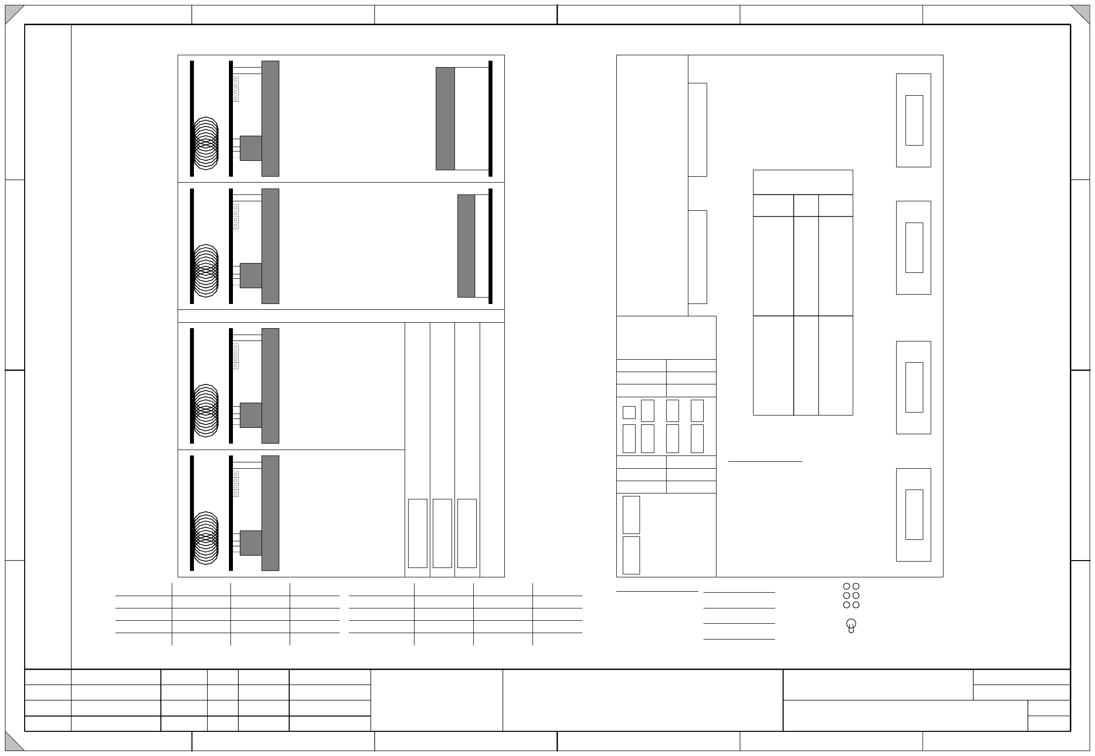
Axis Unit (Front view) Axis Unit (Rear view)
Count Error CE
Zero Pulse 0
End ED
BE
IN
ON
Board Error
Initialized
Servo On
Servo On
Servo OffOFF
Firmware Axis-Card :
X
0
1
_
3
t
q
X
3
1
X
3
2
X
0
2
_
3
t
q
X
0
5
_
3
t
q
X
0
6
_
3
t
q
D
y
n
a
m
i
c
B
r
a
k
e
X
-
A
x
i
s
A
9
A
1
1
D
y
n
a
m
i
c
B
r
a
k
e
Y
-
A
x
i
s
A
1
3
A
1
5
D
y
n
a
m
i
c
B
r
a
k
e
X
-
A
x
i
s
A
1
0
A
1
2
D
y
n
a
m
i
c
B
r
a
k
e
Y
-
A
x
i
s
A
1
4
A
1
6
G
a
n
t
r
y
/
P
o
r
t
a
l
I
V
G
a
n
t
r
y
/
P
o
r
t
a
l
I
X
4
t
a
A
x
i
s
-
C
a
r
d
1
A
x
i
s
-
C
a
r
d
2
X
4
t
b
X
4
t
c
A
x
i
s
-
C
a
r
d
3
X1
Y1
Z1
_1
D
C
/
D
C
-
C
o
n
v
e
r
t
e
r
+
5
V
/
1
5
A
D
C
/
D
C
-
C
o
n
v
e
r
t
e
r
+
/
-
1
5
V
X06_1X05_1
X10_1
S1
X01
_
1
X02_1
X
2
1
_
5
X
2
2
_
5
X
2
3
_
5
X
2
3
4
1
X
2
2
_
4
X
2
1
_
4
X
2
3
4
2
X
3
0
_
2
X
3
0
_
1
X09
_
1
X03
_
1X11
_
1
X12
_1
X08
_1
X04
_1
X07
_1
(tq)
S1 switch settings:
Placement area 1 ADR 4 = 1 by S1
_
1 = OFF
Placement area 2 ADR 4 = 0 by S1
_1 = ON
S1_2 not used.
DP4_2
DP1
_1
X4sr
X4st
X1so
X3so
X5so
X1sp
X3sp
X4vr
X4vt
X1vo
X3vo
X5vo
X1vp
X3vp
Gantry I
Gantry IV
A363 A364Backplane
Axis Unit
Conversion table
for connections
X5sp
X5vp
Gantry/Portal I
A9
A13
Revolver Head
A11
A15 DP1-Axis (DLM)
Z1-Axis (DLM)
empty
Star-Axis
Twin P&P-Head
DP1-Axis
Z1-Axis (Twin)
DP2-Axis
Z2-Axis
(Twin)
(Twin)
(Twin)
VHS Head
DC/DC-Conv.
Gantry/Portal IV
A10
A14
Revolver Head
A12
A16 DP1-Axis (DLM)
Z1-Axis (DLM)
empty
Star-Axis
Twin P&P-Head
DP1-Axis
Z1-Axis (Twin)
DP2-Axis
Z2-Axis
(Twin)
(Twin)
(Twin)
VHS Head
Z1-Axis (VHS)
empty
Star-Axis
DC/DC-Conv.
Z1-Axis (VHS)
empty
Star-Axis
S1
empty
Z1
_
2
DLM
Twin
S4
Z4
_
2
Z4
_1
DLM
Twin
DLM
Twin
X4
Y4
DP4_1
DP1
_2
empty
DLM
Twin
X01_3tq
X02_3tq
X01_1tq
X02_1tq
X03_1tq
X04_1tq
X10_1tq
X05_3tq
X06_3tq
X05_1tq
X06_1tq
X07_1tq
X08_1tq
X11_1tq
X09_1tq
X12_1tq
1
4 - 17
03048004-010101GD4 Label, A364 axis unit, 4-gantry machine (sh. 2 of 3)
03048004-010101GD4
3
07.03.2006
Tekin
Pommer
Schild Axis Unit A364 4-Portal-Maschine
Label axis unit A364 4 gantry machine
SIPLACE X4
Date
Drawn
Checked
StandardsNameModification
Sheet
of
21 6543
A
B
C
D
Date
Designer 9
21 6543
A4
Document No. / Dokumentennummer:
Item name / Benennung
Copyright reserved
Siemens AG
A&D
Stat.
W
e
i
t
e
r
g
a
b
e
s
o
w
i
e
V
e
r
v
i
e
l
f
ä
l
t
i
g
u
n
g
d
i
e
s
e
r
U
n
t
e
r
l
a
g
e
,
V
e
r
w
e
r
t
u
n
g
u
n
d
M
i
t
t
e
i
l
u
n
g
i
h
r
e
s
I
n
h
a
l
t
s
n
i
c
h
t
g
e
s
t
a
t
t
e
t
,
s
o
w
e
i
t
n
i
c
h
t
a
u
s
d
r
ü
c
k
l
i
c
h
z
u
g
e
s
t
a
n
d
e
n
.
Z
u
w
i
d
e
r
h
a
n
d
l
u
n
g
e
n
v
e
r
p
f
l
i
c
h
t
e
n
z
u
S
c
h
a
d
e
n
e
r
s
a
t
z
.
A
l
l
e
R
e
c
h
t
e
v
o
r
b
e
h
a
l
t
e
n
,
i
n
s
b
e
s
o
n
d
e
r
e
f
ü
r
d
e
n
F
a
l
l
d
e
r
P
a
t
e
n
t
e
r
t
e
i
l
u
n
g
o
d
e
r
G
M
-
E
i
n
t
r
a
g
u
n
g
.
P
r
o
p
r
i
e
t
a
r
y
d
a
t
a
,
c
o
m
p
a
n
y
c
o
n
f
i
d
e
n
t
i
a
l
.
A
l
l
r
i
g
h
t
s
r
e
s
e
r
v
e
d
.
C
o
n
f
i
e
a
t
i
t
r
e
d
e
s
e
c
r
e
t
d
'
e
n
t
r
e
p
r
i
s
e
.
T
o
u
s
d
r
o
i
t
s
r
e
s
e
r
v
e
s
.
C
o
m
u
n
i
c
a
d
o
c
o
m
o
s
e
g
r
e
d
o
e
m
p
r
e
s
a
r
i
a
l
.
R
e
s
e
r
v
a
d
o
s
t
o
d
o
s
o
s
d
i
r
e
i
t
o
s
.
C
o
n
f
i
a
d
o
c
o
m
o
s
e
c
r
e
t
e
i
n
d
u
s
t
r
i
a
l
.
N
o
s
r
e
s
e
r
v
a
m
o
s
t
o
d
o
s
l
o
s
d
e
r
e
c
h
o
s
.
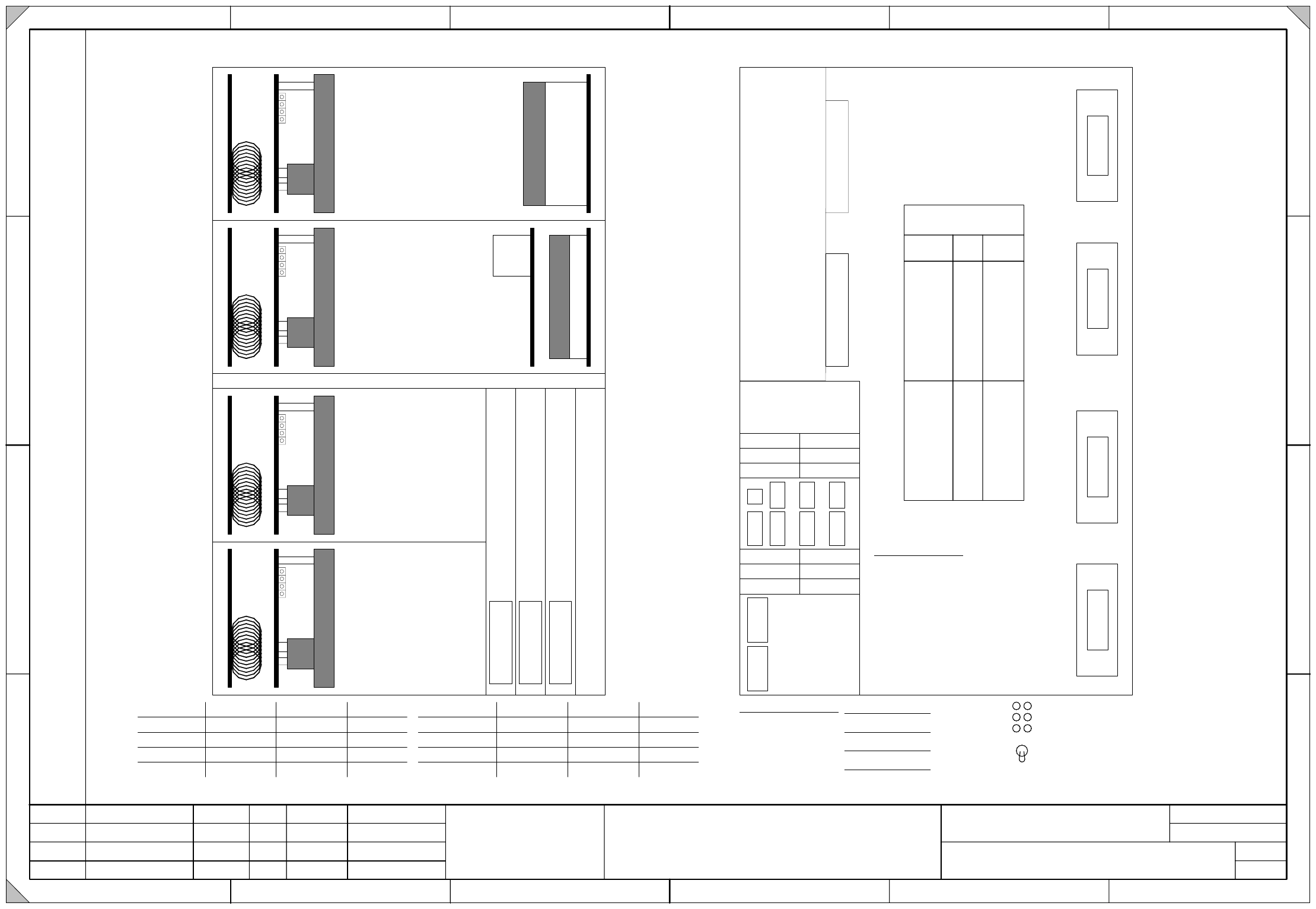
Axis Unit (Rear view)
Count Error CE
Zero Pulse 0
End ED
BE
IN
ON
Board Error
Initialized
Servo On
Servo On
Servo OffOFF
Firmware Axis-Card :
Axis Unit (Front view)
D
y
n
a
m
i
c
B
r
a
k
e
X
-
A
x
i
s
A
9
A
1
1
D
y
n
a
m
i
c
B
r
a
k
e
Y
-
A
x
i
s
A
1
3
A
1
5
D
y
n
a
m
i
c
B
r
a
k
e
X
-
A
x
i
s
A
1
0
A
1
2
D
y
n
a
m
i
c
B
r
a
k
e
Y
-
A
x
i
s
A
1
4
A
1
6
G
a
n
t
r
y
/
P
o
r
t
a
l
I
I
I
G
a
n
t
r
y
/
P
o
r
t
a
l
I
I
0
3
0
4
8
0
0
4
-
0
1
0
1
0
1
G
D
4
S
h
e
e
t
4
(
D
r
u
c
k
v
o
r
l
a
g
e
/
a
r
t
w
o
r
k
)
X
4
s
a
A
x
i
s
-
C
a
r
d
1
A
x
i
s
-
C
a
r
d
2
X
4
s
b
X
4
s
c
A
x
i
s
-
C
a
r
d
3
X
0
1
_
3
s
q
X
2
1
X
2
2
X
0
2
_
3
s
q
X
0
5
_
3
s
q
X
0
6
_
3
s
q
X06_1X05_1
X10_1
S1
X01_1
X02_1
X
2
1
_
5
X
2
2
_
5
X
2
3
_
5
X
2
3
4
1
X
2
2
_
4
X
2
1
_
4
X
2
3
4
2
X
3
0
_
2
X
3
0
_
1
X09_1
X03
_1X11_1
X12
_
1
X08
_1
X04
_
1
X07
_1
(sq)
B
a
l
l
a
s
t
-
C
a
r
d
D
C
/
D
C
-
C
o
n
v
e
r
t
e
r
+
5
V
/
1
5
A
D
C
/
D
C
-
C
o
n
v
e
r
t
e
r
+
/
-
1
5
V
S1 switch settings:
Placement area 1 ADR 4 = 1 by S1
_
1 = OFF
Placement area 2 ADR 4 = 0 by S1
_1 = ON
S1_2 not used.
X4tr
X4tt
X1to
X3to
X5to
X1tp
X4ur
X4ut
X1uo
X3uo
X5uo
X1up
X3up
X3tp
Gantry II
Gantry III
A363 A364Backplane
Axis Unit
Conversion table
for connections
X5tp
X5up
Gantry /
Portal
II
A9
A13
Revolver Head
A11
A15 DP1-Axis (DLM)
Z1-Axis (DLM)
empty
Star-Axis
Twin P&P-Head
DP1-Axis
Z1-Axis (Twin)
DP2-Axis
Z2-Axis
(Twin)
(Twin)
(Twin)
VHS Head
DC/DC-Conv.
Gantry/Portal III
A10
A14
Revolver Head
A12
A16 DP1-Axis (DLM)
Z1-Axis (DLM)
empty
Star-Axis
Twin P&P-Head
DP1-Axis
Z1-Axis (Twin)
DP2-Axis
Z2-Axis
(Twin)
(Twin)
(Twin)
VHS Head
Z1-Axis (VHS)
empty
Star-Axis
DC/DC-Conv.
Z1-Axis (VHS)
empty
Star-Axis
X2
Y2
Z2
_
1
DP3_2
DP2
_1
S2
empty
Z2
_
2
DLM
Twin
S3
Z3
_
2
Z3
_1
DLM
Twin
DLM
Twin
X3
Y3
DP3_1
DP2
_2
empty
DLM
Twin
X01_3sq
X02_3sq
X01_1sq
X02_1sq
X03_1sq
X04_1sq
X09_1sq
X05_3sq
X06_3sq
X05_1sq
X06_1sq
X07_1sq
X08_1sq
X11_1sq
X10_1sq
X12_1sq
2
4 - 18
03048004-010101GD4 Label, A364 axis unit, 4-gantry machine (sh. 3 of 3)
03048004-010101GD4
3
07.03.2006
Tekin
Pommer
Schild Axis Unit A364 4-Portal-Maschine
Label axis unit A364 4 gantry machine
SIPLACE X4
Date
Drawn
Checked
StandardsNameModification
Sheet
of
21 6543
A
B
C
D
Date
Designer 9
21 6543
A4
Document No. / Dokumentennummer:
Item name / Benennung
Copyright reserved
Siemens AG
A&D
Stat.
W
e
i
t
e
r
g
a
b
e
s
o
w
i
e
V
e
r
v
i
e
l
f
ä
l
t
i
g
u
n
g
d
i
e
s
e
r
U
n
t
e
r
l
a
g
e
,
V
e
r
w
e
r
t
u
n
g
u
n
d
M
i
t
t
e
i
l
u
n
g
i
h
r
e
s
I
n
h
a
l
t
s
n
i
c
h
t
g
e
s
t
a
t
t
e
t
,
s
o
w
e
i
t
n
i
c
h
t
a
u
s
d
r
ü
c
k
l
i
c
h
z
u
g
e
s
t
a
n
d
e
n
.
Z
u
w
i
d
e
r
h
a
n
d
l
u
n
g
e
n
v
e
r
p
f
l
i
c
h
t
e
n
z
u
S
c
h
a
d
e
n
e
r
s
a
t
z
.
A
l
l
e
R
e
c
h
t
e
v
o
r
b
e
h
a
l
t
e
n
,
i
n
s
b
e
s
o
n
d
e
r
e
f
ü
r
d
e
n
F
a
l
l
d
e
r
P
a
t
e
n
t
e
r
t
e
i
l
u
n
g
o
d
e
r
G
M
-
E
i
n
t
r
a
g
u
n
g
.
P
r
o
p
r
i
e
t
a
r
y
d
a
t
a
,
c
o
m
p
a
n
y
c
o
n
f
i
d
e
n
t
i
a
l
.
A
l
l
r
i
g
h
t
s
r
e
s
e
r
v
e
d
.
C
o
n
f
i
e
a
t
i
t
r
e
d
e
s
e
c
r
e
t
d
'
e
n
t
r
e
p
r
i
s
e
.
T
o
u
s
d
r
o
i
t
s
r
e
s
e
r
v
e
s
.
C
o
m
u
n
i
c
a
d
o
c
o
m
o
s
e
g
r
e
d
o
e
m
p
r
e
s
a
r
i
a
l
.
R
e
s
e
r
v
a
d
o
s
t
o
d
o
s
o
s
d
i
r
e
i
t
o
s
.
C
o
n
f
i
a
d
o
c
o
m
o
s
e
c
r
e
t
e
i
n
d
u
s
t
r
i
a
l
.
N
o
s
r
e
s
e
r
v
a
m
o
s
t
o
d
o
s
l
o
s
d
e
r
e
c
h
o
s
.
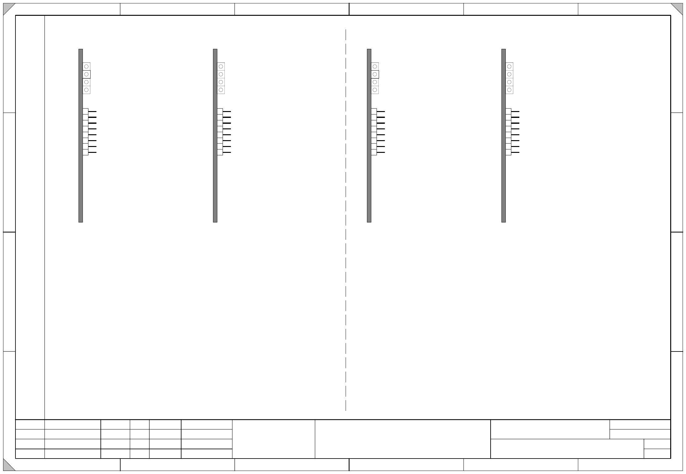
MP1:
MP2:
MP3:
MP4:
MP5:
MP6:
MP7:
MP8:
Strom-Sollwert
Strom-Sollwert
Strom-Istwert
Ausgang Stromregler
Fehlerausgang (analog)
0V Bezugspotential
Strom-Istwert
Ausgang Stromregler
"I-soll (U)"
"I-soll (W)"
"I-ist (U)"
"I-ist (W)"
"U-soll (U)"
"U-Fehler"
"0V"
"U-soll (W)"
Betriebsbereit / Ready
Endstufenfreigabe / Enabled
Effektivstrombegrenzung / Overcurrent
Störung / Error
T
B
S
MP1:
MP2:
MP3:
MP4:
MP5:
MP6:
MP7:
MP8:
Ideal Current Value
Ideal Current Value
Actual Current Value
Current Regulator Output
Error Output (analog)
0V Reference
Actual Current Value
Current Regulator Output
Betriebsbereit / Ready
Endstufenfreigabe / Enabled
Effektivstrombegrenzung / Overcurrent
Störung / Error
S
D
S
Axis Unit (Cards)
MP1:
MP2:
MP3:
MP4:
MP5:
MP6:
MP7:
MP8:
Strom-Sollwert
Strom-Sollwert
Strom-Istwert
Ausgang Stromregler
frei
0V Bezugspotential
Strom-Istwert
Ausgang Stromregler
"I-soll (U)"
"I-soll (W)"
"I-ist (U)"
"I-ist (W)"
"U-soll (U)"
"0V"
"U-soll (W)"
MP1:
MP2:
MP3:
MP4:
MP5:
MP6:
MP7:
MP8:
Ideal Current Value
Ideal Current Value
Actual Current Value
Current Regulator Output
Not Used
0V Reference
Actual Current Value
Current Regulator Output
MP1:
MP2:
MP3:
MP4:
MP5:
MP6:
MP7:
MP8:
Strom-Sollwert
Strom-Sollwert
Strom-Istwert
Ausgang Stromregler
Fehlerausgang (analog)
0V Bezugspotential
Strom-Istwert
Ausgang Stromregler
"I-soll (U)"
"I-soll (W)"
"I-ist (U)"
"I-ist (W)"
"U-soll (U)"
"U-Fehler"
"0V"
"U-soll (W)"
Betriebsbereit / Ready
Endstufenfreigabe / Enabled
Effektivstrombegrenzung / Overcurrent
Störung / Error
T
B
S
MP1:
MP2:
MP3:
MP4:
MP5:
MP6:
MP7:
MP8:
Ideal Current Value
Ideal Current Value
Actual Current Value
Current Regulator Output
Error Output (analog)
0V Reference
Actual Current Value
Current Regulator Output
Betriebsbereit / Ready
Endstufenfreigabe / Enabled
Effektivstrombegrenzung / Overcurrent
Störung / Error
S
D
S
Axis Unit (Cards)
MP1:
MP2:
MP3:
MP4:
MP5:
MP6:
MP7:
MP8:
Strom-Sollwert
Strom-Sollwert
Strom-Istwert
Ausgang Stromregler
frei
0V Bezugspotential
Strom-Istwert
Ausgang Stromregler
"I-soll (U)"
"I-soll (W)"
"I-ist (U)"
"I-ist (W)"
"U-soll (U)"
"0V"
"U-soll (W)"
MP1:
MP2:
MP3:
MP4:
MP5:
MP6:
MP7:
MP8:
Ideal Current Value
Ideal Current Value
Actual Current Value
Current Regulator Output
Not Used
0V Reference
Actual Current Value
Current Regulator Output
03048004-010101GD4
Sheet 5 (Druckvorlage/artwork)
03048004-010101GD4
Sheet 5 (Druckvorlage/artwork)
3