X4电路图.pdf - 第283页
5 - 24 0037039 7-010 101ND 3 TSP 301 (sh. 1 of 2) Date Author Check. Stand. Placeme nt diagram SMD and components with ax ial lea ds Side 1 Stat. Modifi ed Date Name Position for identifica tion label on side 1 a) X3 X3 …
5 - 23
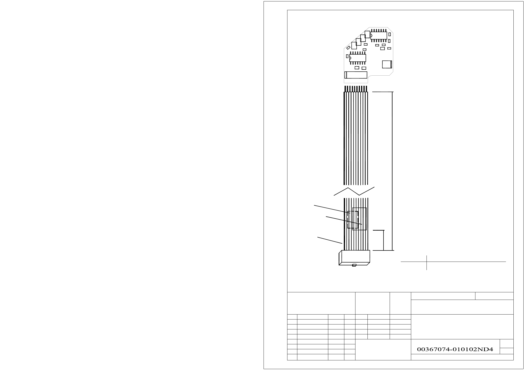
00367074-010102ND4 Adjustment unit 3, placement circuit
besondere für den Fall der Patenterteilung oder GM-Eintragung
pflichten zu Schadenersatz. Alle Rechte vorbehalten, ins
nicht ausdrücklich zugestanden. Zuwiderhandlungen ver-
wertung und Mitteilung ihres Inhalts nicht gestattet, soweit
Weitergabe sowie Vervielfältigung dieser Unterlage,Ver-
A&D
SIEMENS AG
Mayerhofer
ModifiedStat. NameDate
06.11.2001
Standard
Checked
Drawn
Date
Item name / Benennung
Document no. / Unterlagen-Nr. (-FS RS US UA SP F)
Vavle adjustment drive 3 / placement circuit
Name
Scale / Maßstab
Sheet
1
1
Sh.
Format A4
a patent or the registration of a utility model or design.
damages. All rights are reserved in the event of the grant of
out express authority. Offenders are liable to the payment of
or communication of the contents thereof, are forbidden with-
Copying of this document, and giving it to others and the use
Replacement for
Copyright reserved
C4
C2
354.0mm
-5.0mm
Cable, 05-1630-5
B1, B2
Pin 1
A1
X1
50.0mm
C5
R3
R
1
X1
1
C3
+5.0mm
R2
10
R5
U2
R6
R4
U3
R7
X2
X4
X5
X3
U1
C6
readable, when X1 is on the left.
AFO and WIP inspection labels.
50mm distance from cable end.
Readable, when X1 is on the right.
X18 stepping motor board 00344488
May be printed
On the back.
Label position:
on the cable
AssemblyConnector
X1
B1, B2:
Identification label,
A1:
US02 402386 06.03.06 TB
5 - 24
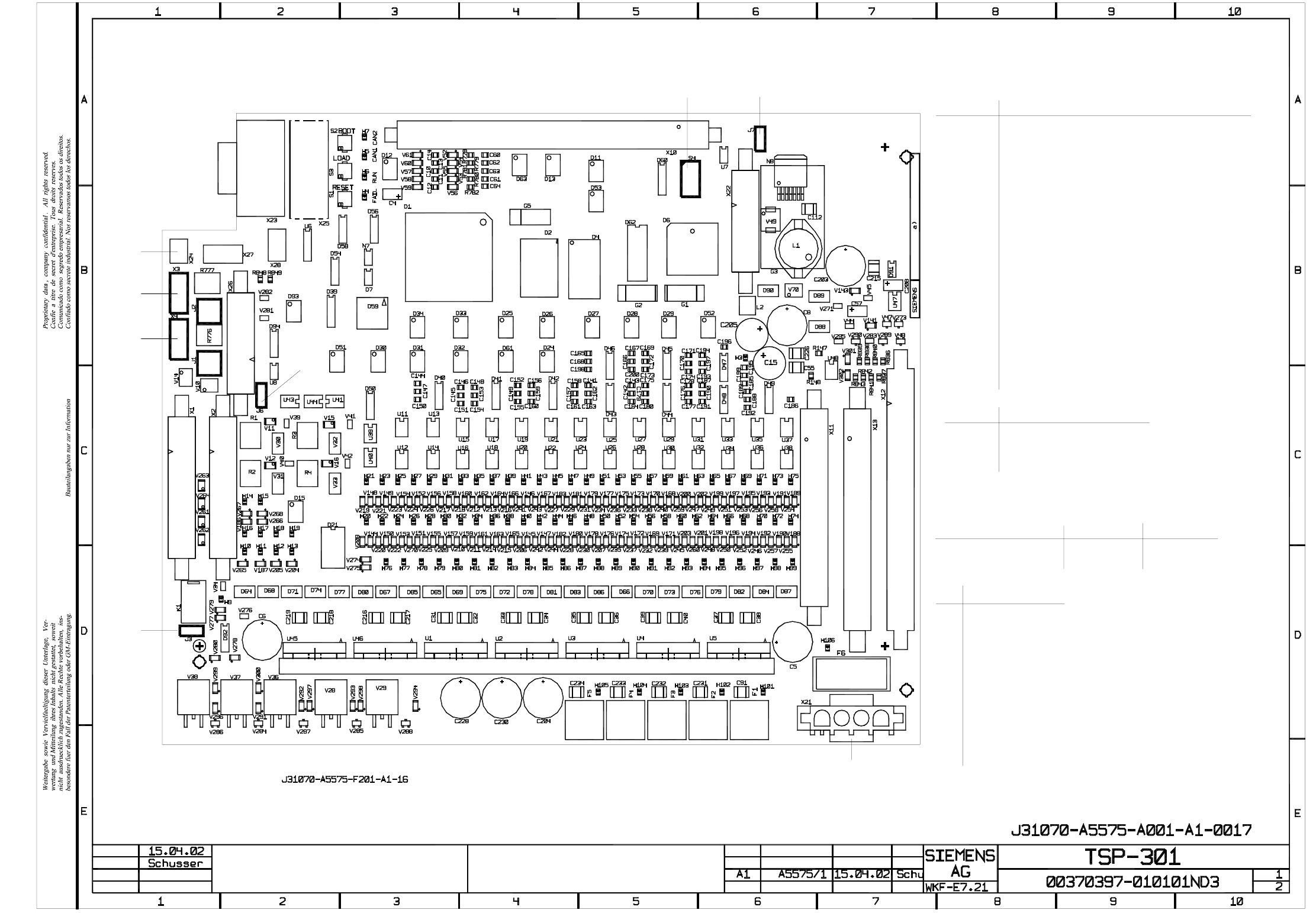
00370397-010101ND3 TSP 301 (sh. 1 of 2)
Date
Author
Check.
Stand.
Placement diagram
SMD and components with axial leads
Side 1
Stat. Modified Date Name
Position for identification label
on side 1
a)
X3
X3
X4
J2
J1
J6
X1 X2
J3
S4 J7
X22
AssemblyConnector
X1
X2
X3
X4
X10
X11
X12
X13
X22
X23
X24
X25
X26
X21
X21:1
X21:2
X21:3
X21:4
Siemens interface, upstream station, conveyor track 1
Siemens interface, downstream station, conveyor track 1
SMEMA interface, upstream station, conveyor track 1
SMEMA interface, downstream station, conveyor track 1
Bus cable to TSP 300E
Conveyor motors, "width adjustment" motor
Sensors/actors
Sensors/actors
Power supply
n.u.
n.u.
RS232 Boot/Debug
GND
CAN bus
CAN bus
n.u.
34 VDC to 42 VDC
24 VDC
Assembly
Fault loop 1-2
CAN bus, pins 2-3
CAN bus, pins 1-2
Jumper
J7
J3
J6
Sh.
Sh.
SIEMENS SMEMA
1-2, 4-5, 7-8 2-3, 5-6, 8-9J1
2-3, 5-6, 8-91-2, 4-5, 7-8J2
J1/J2 interface jumpers, conveyor track 1
Downstream station
Upstream station
Distributor, PCB barcode scanner
X27
F6
X11
X13
X12
X10
X23 X25
X24
X27
X26
F5 F4 F3 F2 F1
X21
S4
OFF
OFF
OFF
OFF
OFF
ON
OFF
ON
2
8
5
6
7
4
3
1
3
OFF from machine no. 56:
up to machine no. 55:
clamping detection via clamping sensor
clamping detection via motor current measurement
Copyright reserved
5 - 25
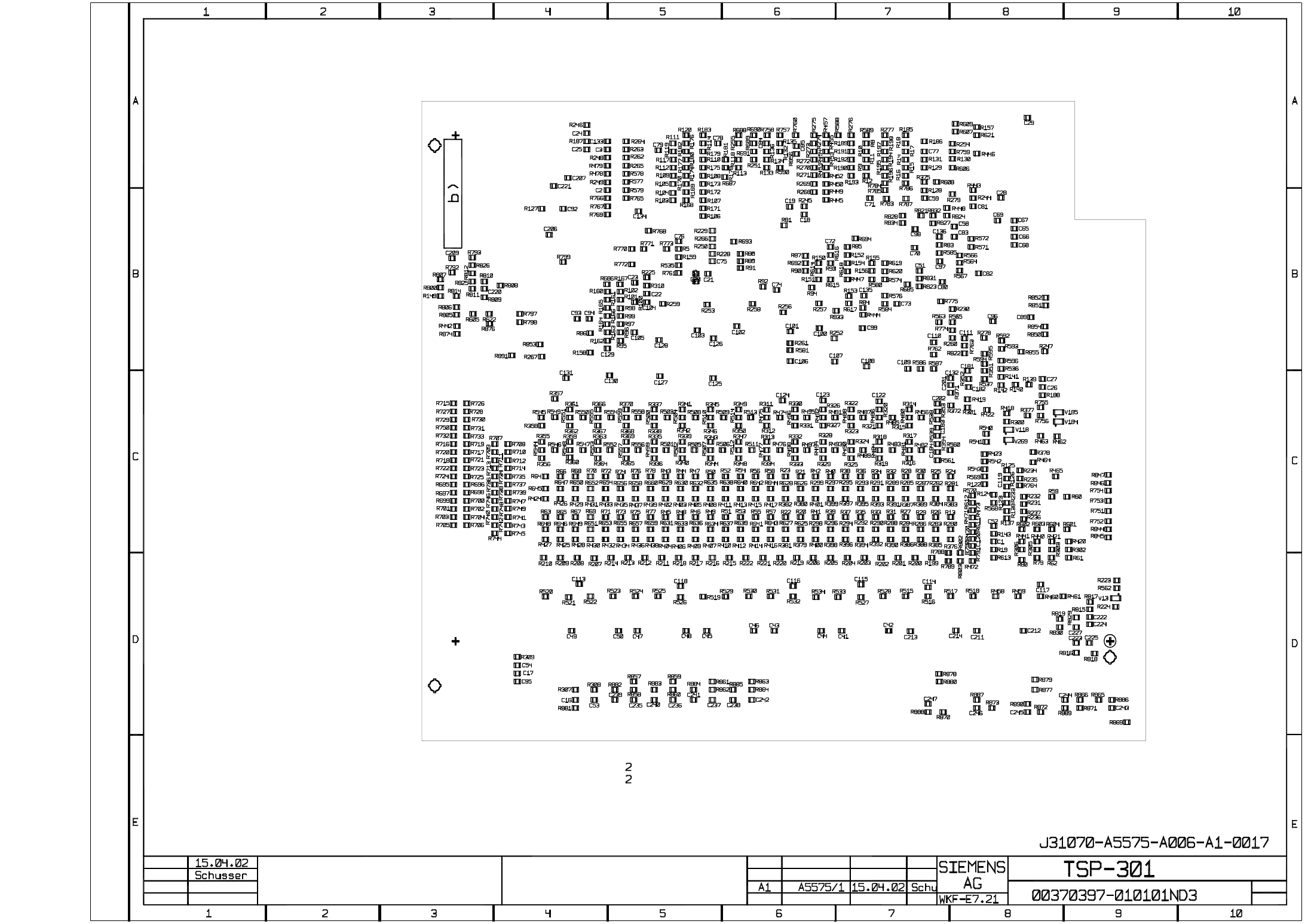
00370397-010101ND3 TSP 301 (sh. 2 of 2)
Bauteilangaben nur zur Informationbesondere fuer den Fall der Patenterteilung oder GM-Eintragung.
nicht ausdruecklich zugestanden. Alle Rechte vorbehalten, ins-
wertung und Mitteilung ihres Inhalts nicht gestattet, soweit
Weitergabe sowie Vervielfaeltigung dieser Unterlage, Ver-
Confiado como secrete industrial. Nos reservamos todos los derechos.
Proprietary data , company confidential . All rights reserved.
Confie a titre de secret d'entreprise. Tous droits reserves.
Comunicado como segredo empresarial. Reservados todos os direitos.
b) Position for inspection label
on side 2
Stand.
Date
Check.
Author
SMD side 2 + 4 x spacer
Placement diagram
State Modified Date
Name
Sh. 2
Sh. 2
Copyright reserved