X4电路图.pdf - 第330页
6 - 5 0303805 8-010 102XD0 Pneu matic u nit, SIPL ACE X-S eries, p neumati c system (sh. 1 of 3 ) PUN 6 x 1 (0 .3m) 03004677-x x PUN 6 x 1 (0 .3m) 03004677-x x PUN 8 x 1.25 (1 .2m ) 03006587-x x PUN 8 x 1.25 (1 .0m ) 030…
6 - 4
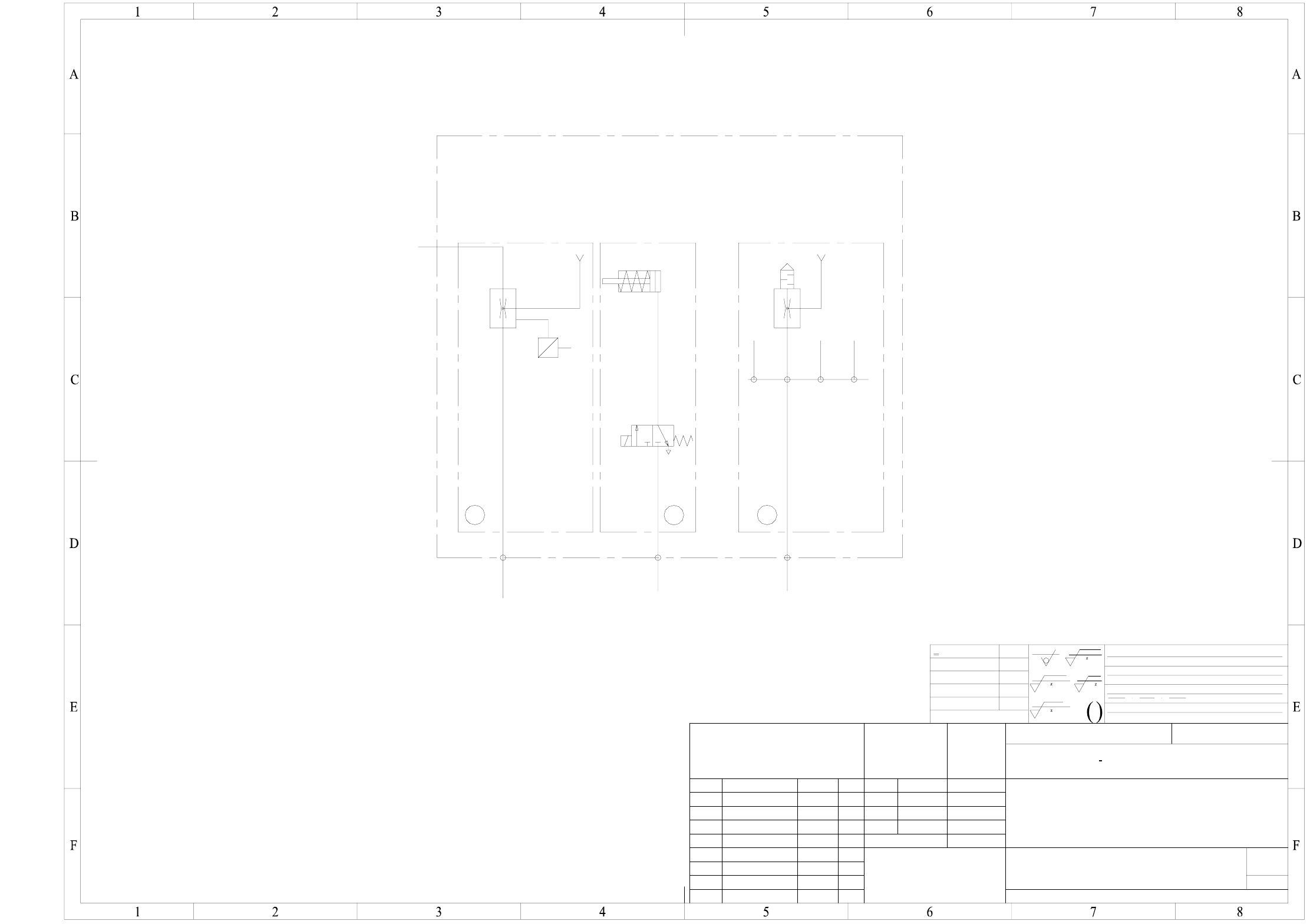
03008827-010101XD3 C&P20 placement head, pneumatic diagram, SIPLACE X-series
(20x)
2.5 - 4.5 bar, 120 to 200 st.l/min
VHS
Return motion cyl.
Z axis
Placement circuit
X
P
V
2
13
Holding circuit
4.5 + 0.1 bar, 50 st.l/min.
To gantry cooling system
Drawings 2/A
Weitergabe sowie Vervielfältigung dieser Unterlage, Verwer-
oder GM-Eintragung vorbehalten.
Schadenersatz. Alle Rechte für den Fall der Patenterteilung
ausdrücklich zugestanden. Zuwiderhandlungen verpflichten zu
tung und Mitteilung ihres Inhalts nicht gestattet, soweit nicht
a patent or the registration of a utility model or design.
damages. All rights are reserved in the event of the grant of
out express authority. Offenders are liable to the payment of
or communication of the contents thereof, are forbidden with-
Copying of this document, and giving it to others and the use
NameDateModifiedStatus
DS 01
new nn.nn.nn - - -
(Material, semi-fin. products)
Degree of accuracy
FMain no. FS PS DS DT L
03008827-010101XD3
(Drawing number)
Pneumatic diagram
C&P20 placement head
(Unmachined part no.)
(Model or swage no.)
Stand.
Schmid R.
Name
Date
26.02.04
Author
Check.
acc. to ISO 2768 mH
medium
Sheet
Sh.
1
1
1710xxx Xxxxx xxx xx P
Depth:0.3/
2-5 um layer (nickel-plated)
R 100
R 25
>30...120
±0.3
>120...400
>400...1000
Dimens. variations
Dimens. variations:
Scale:
±0.5
±0.8
>6...30
<6
±0.2
±0.1
HRc tempered
R 1
NN ± N
case hardened
Coordinates list:
Comprising
Format
R 6.3
Surface.:
A3
SIPLACE X-Series
PL EA
Copyright reserved
SIEMENS
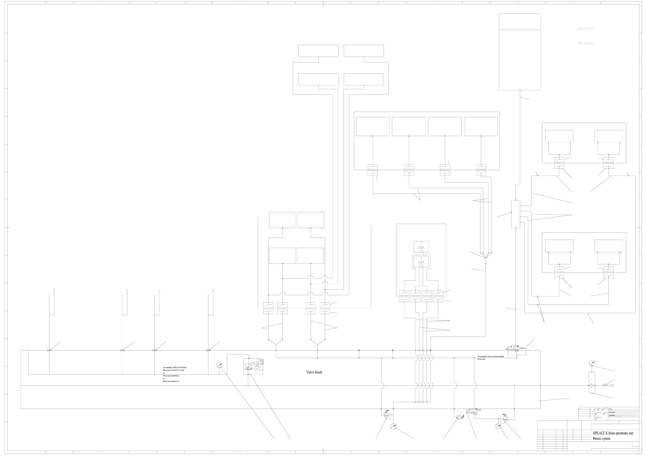
6 - 5
03038058-010102XD0 Pneumatic unit, SIPLACE X-Series, pneumatic system (sh. 1 of 3)
PUN 6 x 1 (0.3m)
03004677-xx
PUN 6 x 1 (0.3m)
03004677-xx
PUN 8 x 1.25 (1.2m)
03006587-xx
PUN 8 x 1.25 (1.0m)
03004147-xx
PUN 8 x 1.25 (1.2m)
03006587-xx
Pressure required
p = 4.6 +0.1 bar
Adju st at internal po tentiometer
possible
Proportional valve
p = 5.0 ±0.1 bar
Feeder unlocking rail
SP 4
Feeder unlocking rail
SP 3
Feeder unlocking rail
SP 1
Feeder unlocking rail
SP 2
Multiple distributor
QSQ-6-4
00336911-xx
= Siemens BOM item no.
03038058-xx
Hose connection
RTU-PK-4/6
00047026-xx
Interface
Compr. air supply, dock. unit
03004200-01
Hose connection
RTU-PK-4/6
00047026-xx
Hose connection
RTU-PK-4/6
00047026-xx
PUN 10 x 1.5
03004139-xx
Interface, CO dock. unit
(Sockets)
03004679-xx
Interface, CO dock. unit
(Sockets)
03004679-xx
Interface, CO dock. unit
(Sockets)
03004679-xx
Interface, CO dock. unit
(Sockets)
03004679-xx
Interface
Compr. air supply, dock. unit
03004200-01
PUN 4 x 0.75 (1.9m)
03006588-xx
PUN 4 x 0.75 (1.6m)
03004145-xx
PUN 6 x 1.00 (0.4m)
03006589-xx
PUN 4 x 0.75 (2.0m)
03004143-xx
PUN 4 x 0.75 (2.2m)
03006583-xx
PUN 6 x 1.00 (1.8m)
03004146-xx
PUN 6 x 1.00 (2.0m)
03006585-xx
= Siemens and Asco BOM item no.
SIPLACE D3 control block
(03038355-xx)
03038058-010102XD0
SP 2
SP 3
max.50 st.l/min.
SP 4
SP 1
B23.3
B23.2
B23.1
B23.4
B22
Gantry 4 Gantry 1
Gantry 2
Gantry 3
B13.2
B13.1
B1
B11
B9
B10.4
B10.3
B10.2
B10.1
B7 B8
B6
B2
B3
B4
B5
B14
B20
B13.2B13.2
B21
S1
M1
M2
max.50 st.l/min.
SP 3 SP 2
SP 4 SP 1
max.255 st.l/min.
Lift. table 1
Lift. table 2
Width adjustment
Consumption not relevant
PCB stopper (option)
Consumption not relevant
255 st.l/min.
SP = location
Desired input pressure: 5 bar
Chan ge
Request No.
Accuracy principle
DIN 7167
General tolerance s for
nomin al dime nsions without
spec. tolerance
ISO 2768 mH
Ceramic substrate centering
(Option)
DC SIPLACE HF, 00119670-xx
SC SIPLACE HF, 00119671-xx
Lifting tables 3 and 4
in dual conveyor system
Modular single conveyor
00119625-xx
Modular dual conveyor
00119627-xx
PUN 8 x 1.25 (xxxm)
03004138-xx
Consumption not relevant
Can't be operated
during placement
Trolley dock. unit
03000811-xxxxxx
Consumption not relevant
Can't be operated
during placement
Trolley dock. unit
03000811-xxxxxx
Consumption not relevant
Can't be operated
during placement
Trolley dock. unit
03000811-xxxxxx
Consumption not relevant
Can't be operated
during placement
Trolley dock. unit
03000811-xxxxxx
p = 5 to 10 bar
at an air consmpt. of 1800st.l/min.
Interface
Compr. air supply, dock. unit
03004200-xx
Connection for
Bulk case
Feeder
(Option)
up to max. 2 per SP
Consumption not relevant
Nozzle changer (option)
(12-seg. RV 03001855-xx
6-seg. RV 03004010-xx
VHS)
up to max. 2 per SP
Consumption not relevant
Nozzle changer (option)
(12-seg. RV 03001855-xx
6-seg. RV 03004010-xx
VHS)
up to max. 2 per SP
Consumption not relevant
Nozzle changer (option)
(12-seg. RV 03001855-xx
6-seg. RV 03004010-xx
VHS)
up to max. 2 per SP
Consumption not relevant
Nozzle changer (option)
(12-seg. RV 03001855-xx
6-seg. RV 03004010-xx
VHS)
Interface
Compr. air supply, dock. unit
03004200-xx
Copying of this document, and giving it to others and the use
or communication of the contents thereof, are forbidden with-
out express authority. Offenders are liable to the payment of
damages. All rights are reserved in the event of the grant of
a patent or the regis tration of a utility model or design.
Weitergabe sowie Vervielfältigung dieser Unterlage, Verwer-
tung und Mitteilung ihres Inhalts nicht gestattet, soweit nicht
ausdrücklich zugestanden. Zuwiderhandlungen verpflichten zu
Schade nersatz. Alle Rechte für den F all der Patenterteilung
oder GM-Eintragung vorbehalten.
Tape cutter
03019941-xxxxxx
Tape cutter
03019941-xxxxxx
Interface
Compr. air supply, dock. unit
03004200-xx
Tape cutter
03019941-xxxxxx
Tape cutter
03019941-xxxxxx
Interface
Compr. air supply, dock. unit
03004200-xx
DS +01 E CO 402145 22.02. 2006 HS
A&D
<6
>6...30
>30...120
>120...400
>400...1000
±0.1
±0.2
±0.3
±0.5
±0.8
z
R 100
z
R 25
z
R 6.3
z
R 1
22
K
I
H
G
F
E
D
C
B
A
151413121110987654321 16 17 18 19 20 21 22
151413121110987654321 16 17 18 19 20 21
L
M
N
O
P
R
K
I
H
G
F
E
D
C
B
A
L
M
N
O
P
R
Copyrig ht reserved
Sheet
of
Material
Format
Document - No. (FS RS DS DT L F) / Unterlagen - Nr. (FS RS US UA SP F)
Scal e
Stan dard s
Checked
Drawn
Date Name
General tolerances
NameDateModifi cation / E CO no.
Siemens AG
Replacement for
)(
A0
2-5 um nickel-plated (chem.)
1
3
Schönbach07.03.05
A0
SP 3
2.5 bar
2.5 bar
PUN-4 x 0.75
PUN-4 x 0.75
2.5 bar
2.5 bar
PUN-4 x 0.75
PUN-4 x 0.75
Cover up connections in HF machines
SP 4SP 2SP 1
1/4" 5 x M51/8"1/4"1/4"1/2"1/2"1/2"1/2"1/8"
3/4"3/4"
Main hole >3/4"
X
X
X60
2
3
4
1
5
Safety valve
255 + 138 st.l/min. PUN 10
Distributor
V5e1
PUN-6
PUN-6
PUN-6
PUN-6
SP 3
max. 138 st.l/min.
4.5 bar 4.5 bar
SP 4
max. 138 st.l/min.
PUN-6
PUN-6
PUN-6
PUN-6
SP 2
max. 138 st.l/min.
4.5 bar 4.5 bar
SP 1
max. 138 st.l/min.
Press. switch
X59
X59
Main valve
bA
2
3
4
1
5
140140 140 140
110/120/150
70 500 80
100
9070 7050 40
60
30
10
03004151-xx
03004088-xx
10S
3S
2S
See sheets 2 and 3 See sheets 2 and 3 See sheets 2 and 3 See sheets 2 and 3
Consumption not relevantConsumption not relevant
Consumption not relevant
PUN-4 x 0.75
PUN-4 x 0.75
PUN-4 x 0.75
Consumption not relevant
PUN-4 x 0.75
5um
p = 5.0 ±0.25 bar
p = 2.5 ± 0.5 bar
X58
X
V
P
D
A
external
inter nal
NOM value
8 bit
digital
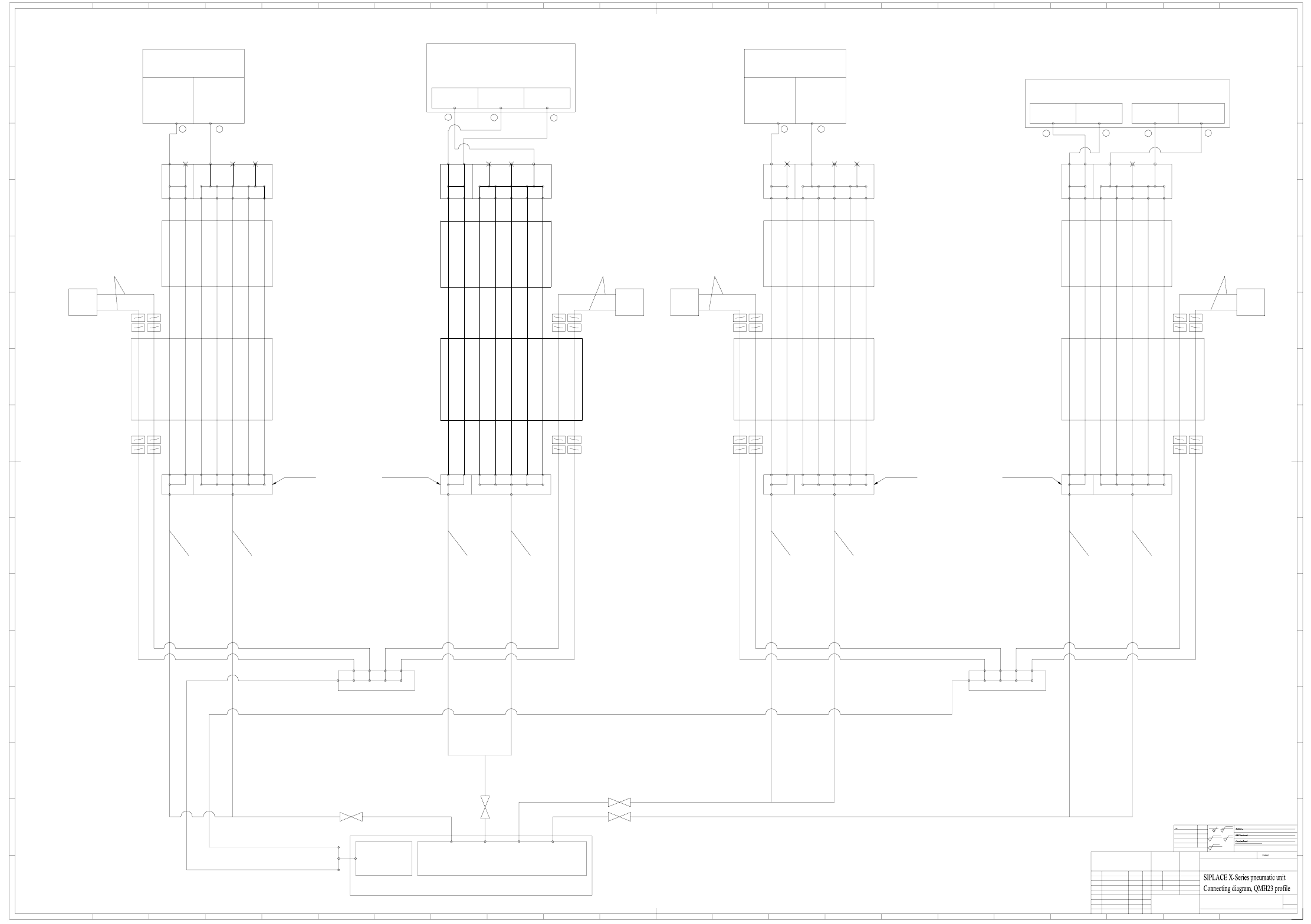
6 - 6
03038058-010102XD0 Pneumatic unit, SIPLACE X-Series,
connecting diagram, QMH23 profile (sh. 2 of 3)
6-M7 4-M7 4-M7 8-1/4" 8-1/4"
V3a1
V3a2
V3a3
V3a4
V3a5
Y
V3e1
V3e2
V3e3
V3e4
V3e5
V3e6
V3e7
V4e1
V4e2
V4e3
V4e4
V4e5
V4e6
V4e7
V4a5
V4a4
V4a3
V4a2
V4a1
8-1/4"8-1/4"4-M74-M76-M7
Y
XX
6-M7 4-M7 4-M7 8-1/4" 8-1/4"
V3a1
V3a2
V3a3
V3a4
V3a5
Y
V3e1
V3e2
V3e3
V3e4
V3e5
V3e6
V3e7
V4e1
V4e2
V4e3
V4e4
V4e5
V4e6
V4e7
V4a5
V4a4
V4a3
V4a2
V4a1
8-1/4"8-1/4"4-M74-M76-M7
Y
XX
Gantry 1 Gantry 2 Gantry 3 Gantry 4
Replacement for
Siemens AG
Modification / ECO no. Date Name
General tolerances
NameDate
Drawn
Checked
Standards
Scale
Document - No. (FS RS DS DT L F) / Unterlagen - Nr. (FS RS US UA SP F)
Material
of
Forced air
Plcmt. circuit
Holding circuit
1
2
4.5 +0.1 bar, 200 st.l/min.
Air consmpt.:5st.l/min
Forced air
Plcmt. circuit
Holding circuit
1
2
4.5 +0.1 bar, 200 st.l/min.
Air consmpt.:5st.l/min
1
2
Vacuum generator
1
2
4.5 ± 0.1 bar, 100 st.l/min.
Vacuum generator
V2e1 V2e2
V2a7
V2a6
V2a5
V2a4
V2a3
V2a2
V2a1
V1e2V1e1
V1a7
V1a6
V1a5
V1a4
V1a3
V1a2
V1a1
for SIPLACE HFfor SIPLACE HF
V2e1 V2e2
V2a7
V2a6
V2a5
V2a4
V2a3
V2a2
V2a1
V1e2V1e1
V1a7
V1a6
V1a5
V1a4
V1a3
V1a2
V1a1
for SIPLACE HFfor SIPLACE HF
Sheet
Copyright reserved
R
P
O
N
M
L
A
B
C
D
E
F
G
H
I
K
R
P
O
N
M
L
2120191817161 23456789101112131415
222120191817161 23456789101112131415
A
B
C
D
E
F
G
H
I
K
22
R 1
z
R 6.3
z
R 25
z
R 100
z
±0.8
±0.5
±0.3
±0.2
±0.1
>400...1000
>120...400
>30...120
>6...30
<6
A&D
HS22.02.2006E CO 402145DS +01
3
2
2-5 um nickel-plated (chem.)
A0
()
Schönbach07.03.05
03038058-010102XD0
A0
Ø 12 Ø 12 Ø 12 Ø 12 Ø 12 Ø 12 Ø 12 Ø 12
Y motor Y motor Y motor Y motor
X cable and hose carrierX cable and hose carrierX cable and hose carrier X cable and hose carrier
3
VHS head
Holding circuit
1
2
Return motion cyl.
Plcmt. circuit
Plcmt. circuit + return motion cyl.
4.5 ± 0.1 bar, 50 st.l/min.
Holding circuit
2.5 - 4.5 bar, 120 to 200 st.l/min
Y cable and hose carrier
QMH23 profile
Y cable and hose carrier
QMH23 profile
Y cable and hose carrier
QMH23 profile
Pneumatic hose 03005790-xx
TUS1208 Soft PU 12x8 ( 0.32m )
Pneumatic hose 03005790-xx
TUS1208 Soft PU 12x8 ( 0.22m )
Pneumatic hose 03005790-xx
TUS1208 Soft PU 12x8 ( 0.32m )
Pneumatic hose 03005790-xx
TUS1208 Soft PU 12x8 ( 0.22m )
Pneumatic hose 03005790-xx
TUS1208 Soft PU 12x8 ( 0.25m )
Pneumatic hose 03005790-xx
TUS1208 Soft PU 12x8 ( 0.25m )
Pneumatic hose 03005790-xx
TUS1208 Soft PU 12x8 ( 0.25m )
Pneumatic hose 03005790-xx
TUS1208 Soft PU 12x8 ( 0.25m )
Y cable and hose carrier
QMH23 profile
Cooling air distributor, D3
03005409-xx
Cooling air distributor, D3
03005409-xx
Accu racy prin ciple
DIN 7167
Weitergabe sowie Vervielfältigung dieser Unterlage, Verwer-
tung u nd Mitteilu ng ihres Inha lts nicht gestattet, soweit nicht
ausdrücklich zugestanden. Zuwiderhandlungen verpflichten zu
Scha denersatz. All e Rechte für de n Fall der Patenterteilung
oder GM-Eintragung vorbehalten.
Copying of this document, and giving it to others and the use
or communication of the contents thereof, are forbidden with-
out expr ess authority . Offenders are liable to the payment of
dam ages. All r ights are re serv ed in t he event o f the gr ant of
a patent or the registration of a utility model or design.
Change
Request No.
General toleran ces for
nomi nal dimensio ns without
spec. tolerance
ISO 2768 mH
PVC hose with woven fabric inlay
Ø 16x4
PVC hose with woven fabric inlay
Ø 16x4
Fan unit
(Elmo)
03006294-xx
Pneumatic unit, SIPLACE D3
03038058-xx
Valve block, SIPLACE D3
03038355-xx
Hose 03012081-xx
made of
TFU0604B-8-10-X17 (SMC)
Hose 03012081-xx
made of
TFU0604B-8-10-X17 (SMC)
Hose 03012081-xx
made of
TFU0604B-8-10-X17 (SMC)
Hose 03012081-xx
made of
TFU0604B-8-10-X17 (SMC)
Distributor, placement head
03013015-xx
Distributor, placement head
03013015-xx
Distributor, placement head
03013015-xx
Distributor, placement head
03013015-xx
for SIPLACE X-F, X-S
and X-HS
Gantry distributor
SIPLACE X-HS
03006853-xx
Gantry distributor cpl.
03004080-01
for SIPLACE X-F, X-S
and X-HS
Gantry distributor
SIPLACE X-HS
03006853-xx
Gantry distributor cpl.
03004080-01
for SIPLACE X-F, X-S
and X-HS
Gantry distributor
SIPLACE X-HS
03006853-xx
Gantry distributor cpl.
03004080-01
for SIPLACE X-F, X-S
and X-HS
Gantry distributor
SIPLACE X-HS
03006853-xx
Gantry distributor cpl.
03004080-01
Return motion cyl.
Z axis
Return motion cyl.
Z axis
Twin Pick+Place head
03001841-xx
Revolver head DLM2-6, 00367020-xx
Revolver head DLM2-12, 00367281-xx
Ø-No zzle 1 mm
Suct . pwr.:27N/l
Air consmpt.:55st.l/min
Ø-Nozzle 1.5mm
Suct. pwr.:63N/l
Air consmpt.:140st.l/min
Revolver head DLM2-6, 00367020-xx
Revolver head DLM2-12, 00367281-xx
Ø-Nozzle 1mm
Suct. pwr.:27N/l
Air consmpt.:55st.l/min
Ø-Nozzle 1.5mm
Suct. pwr.:63N/l
Air consmpt.:140st.l/min
PUN 12 x 2.0 (1.9m)
03004179-xx
PUN 10 x 1.5 (1.9m)
03004178-xx
PUN 12 x 2.0 (1.9m)
03004179-xx
PUN 10 x 1.5 (1.9m)
03004178-xx
PUN 12 x 2.0 (2.5m)
03004181-xx
PUN 10 x 1.5 (2.5m)
03004180-xx
PUN 12 x 2.0 (2.5m)
03004181-xx
PUN 10 x 1.5 (2.5m)
03004180-xx