X4电路图.pdf - 第55页
2 - iv SIPLA CE X-Se ries De tai led Ci rcuit D iagra ms Fold er 08/2006 US Editi on convers ion board „Convey or“ (sh. 3 o f 8) 2 - 150 LPDT-020 101LD3 PCB dual conve yor, tra ck 2 convers ion board „Convey or“ (sh. 4 o…
SIPLACE X-Series Detailed Circuit Diagrams Folder
08/2006 US Edition
2 - iii
DP04_612X3X4-020101LD3 DP axis, 6/12-segment C&P head, gantry 4, SIPLACE X3 and X4 (sh. 1 of 2) 2 - 108
DP04_612X3X4-020101LD3 DP axis, 6/12-segment C&P head, gantry 4, SIPLACE X3 and X4 (sh. 2 of 2) 2 - 109
P01_20X2-020101LD3 Return motion unit, CO sensor, pressure control valve, pressure sensor,
20-segment Collect&Place head, gantry 1, SIPLACE X2 2 - 110
P01_20X3X4-020101LD3 Return motion unit, CO sensor, pressure control valve, pressure sensor,
20-segment Collect&Place head, gantry 1, SIPLACE X3 and X4 2 - 111
P02_20X4-020101LD3 Return motion unit, CO sensor, pressure control valve, pressure sensor,
20-segment Collect&Place head, gantry 2, SIPLACE X4 2 - 112
P03_20X2X3-020101LD3 Return motion unit, CO sensor, pressure control valve, pressure sensor,
20-segment Collect&Place head, gantry 3, SIPLACE X2 and X3 2 - 113
P03_20X4-020101LD3 Return motion unit, CO sensor, pressure control valve, pressure sensor,
20-segment Collect&Place head, gantry 3, SIPLACE X4 2 - 114
P04_20X3X4-020101LD3 Return motion unit, CO sensor, pressure control valve, pressure sensor,
20-segment Collect&Place head, gantry 4, SIPLACE X3 and X4 2 - 115
ZTH011_X2-020101LD3 Z1 axis, TwinHead, P&P module 1, gantry 1, SIPLACE X2 (sh. 1 of 3) 2 - 116
ZTH011_X2-020101LD3 Z1 axis, TwinHead, P&P module 1, gantry 1, SIPLACE X2 (sh. 2 of 3) 2 - 117
ZTH011_X2-020101LD3 Z1 axis, TwinHead, P&P module 1, gantry 1, SIPLACE X2 (sh. 3 of 3) 2 - 118
ZTH012_X2-020101LD3 Z2 axis, TwinHead, P&P module 2, gantry 1, SIPLACE X2 (sh. 1 of 3) 2 - 119
ZTH012_X2-020101LD3 Z2 axis, TwinHead, P&P module 2, gantry 1, SIPLACE X2 (sh. 2 of 3) 2 - 120
ZTH012_X2-020101LD3 Z2 axis, TwinHead, P&P module 2, gantry 1, SIPLACE X2 (sh. 3 of 3) 2 - 121
ZTH031_X2X3-020101LD3 Z1 axis, TwinHead, P&P module 1, gantry 3, SIPLACE X2 and X3 (sh. 1 of 3) 2 - 122
ZTH031_X2X3-020101LD3 Z1 axis, TwinHead, P&P module 1, gantry 3, SIPLACE X2 and X3 (sh. 2 of 3) 2 - 123
ZTH031_X2X3-020101LD3 Z1 axis, TwinHead, P&P module 1, gantry 3, SIPLACE X2 and X3 (sh. 3 of 3) 2 - 124
ZTH032_X2X3-020101LD3 Z2 axis, TwinHead, P&P module 2, gantry 3, SIPLACE X2 and X3 (sh. 1 of 3) 2 - 125
ZTH032_X2X3-020101LD3 Z2 axis, TwinHead, P&P module 2, gantry 3, SIPLACE X2 and X3 (sh. 2 of 3) 2 - 126
ZTH032_X2X3-020101LD3 Z2 axis, TwinHead, P&P module 2, gantry 3, SIPLACE X2 and X3 (sh. 3 of 3) 2 - 127
DPTH011_X2-020101LD3 DP1 axis, TwinHead, P&P module 1, gantry 1, SIPLACE X2 (sh. 1 of 3) 2 - 128
DPTH011_X2-020101LD3 DP1 axis, TwinHead, P&P module 1, gantry 1, SIPLACE X2 (sh. 2 of 3) 2 - 129
DPTH011_X2-020101LD3 DP1 axis, TwinHead, P&P module 1, gantry 1, SIPLACE X2 (sh. 3 of 3) 2 - 130
DPTH012_X2-020101LD3 DP2 axis, TwinHead, P&P module 2, gantry 1, SIPLACE X2 (sh. 1 of 3) 2 - 131
DPTH012_X2-020101LD3 DP2 axis, TwinHead, P&P module 2, gantry 1, SIPLACE X2 (sh. 2 of 3) 2 - 132
DPTH012_X2-020101LD3 DP2 axis, TwinHead, P&P module 2, gantry 1, SIPLACE X2 (sh. 3 of 3) 2 - 133
DPTH031_X2X3-020101LD3 DP1 axis, TwinHead, P&P module 1, gantry 3, SIPLACE X2 and X3 (sh. 1 of 3) 2 - 134
DPTH031_X2X3-020101LD3 DP1 axis, TwinHead, P&P module 1, gantry 3, SIPLACE X2 and X3 (sh. 2 of 3) 2 - 135
DPTH031_X2X3-020101LD3 DP1 axis, TwinHead, P&P module 1, gantry 3, SIPLACE X2 and X3 (sh. 3 of 3) 2 - 136
DPTH032_X2X3-020101LD3 DP2 axis, TwinHead, P&P module 2, gantry 3, SIPLACE X2 and X3 (sh. 1 of 3) 2 - 137
DPTH032_X2X3-020101LD3 DP2 axis, TwinHead, P&P module 2, gantry 3, SIPLACE X2 and X3 (sh. 2 of 3) 2 - 138
DPTH032_X2X3-020101LD3 DP2 axis, TwinHead, P&P module 2, gantry 3, SIPLACE X2 and X3 (sh. 3 of 3) 2 - 139
LPET-020101LD3 PCB single conveyor / PCB dual conveyor, track 1
conveyor control TSP 301 (sh. 1 of 8) 2 - 140
LPET-020101LD3 PCB single conveyor / PCB dual conveyor, track 1
conveyor control TSP 301 (sh. 2 of 8) 2 - 141
LPET-020101LD3 PCB single conveyor / PCB dual conveyor, track 1
conversion board "conveyor" (sh. 3 of 8) 2 - 142
LPET-020101LD3 PCB single conveyor / PCB dual conveyor, track 1
conversion board "conveyor" (sh. 4 of 8) 2 - 143
LPET-020101LD3 PCB single conveyor / PCB dual conveyor, track 1
conversion board "conveyor" (sh. 5 of 8) 2 - 144
LPET-020101LD3 PCB single conveyor / PCB dual conveyor, track 1
conversion board „Transportation cheek A“ (sh. 6 of 8) 2 - 145
LPET-020101LD3 PCB single conveyor / PCB dual conveyor, track 1
conversion board „Transportation cheek B“ (sh. 7 of 8) 2 - 146
LPET-020101LD3 PCB single conveyor / PCB dual conveyor, track 1
conversion board „Lifting table", placement sectors 1 (sh. 8 of 8) 2 - 147
LPDT-020101LD3 PCB dual conveyor, track 2
conveyor control TSP -301E (sh. 1 of 8) 2 - 148
LPDT-020101LD3 PCB dual conveyor, track 2
conveyor control TSP -301E (sh. 2 of 8) 2 - 149
LPDT-020101LD3 PCB dual conveyor, track 2
2 - iv
SIPLACE X-Series Detailed Circuit Diagrams Folder
08/2006 US Edition
conversion board „Conveyor“ (sh. 3 of 8) 2 - 150
LPDT-020101LD3 PCB dual conveyor, track 2
conversion board „Conveyor“ (sh. 4 of 8) 2 - 151
LPDT-020101LD3 PCB dual conveyor, track 2
conversion board „Conveyor“ (sh. 5 of 8) 2 - 152
LPDT-020101LD3 PCB dual conveyor, track 2
conversion board „Transportation cheek C“ (sh. 6 of 8) 2 - 153
LPDT-020101LD3 PCB dual conveyor, track 2
conversion board „Transportation cheek D“ (sh. 7 of 8) 2 - 154
LPDT-020101LD3 PCB dual conveyor, track 2
conversion board „Lifting table", placement sectors 1 + 2 (sh. 8 of 8) 2 - 155
2 - 1
2 Detailed circuit diagrams
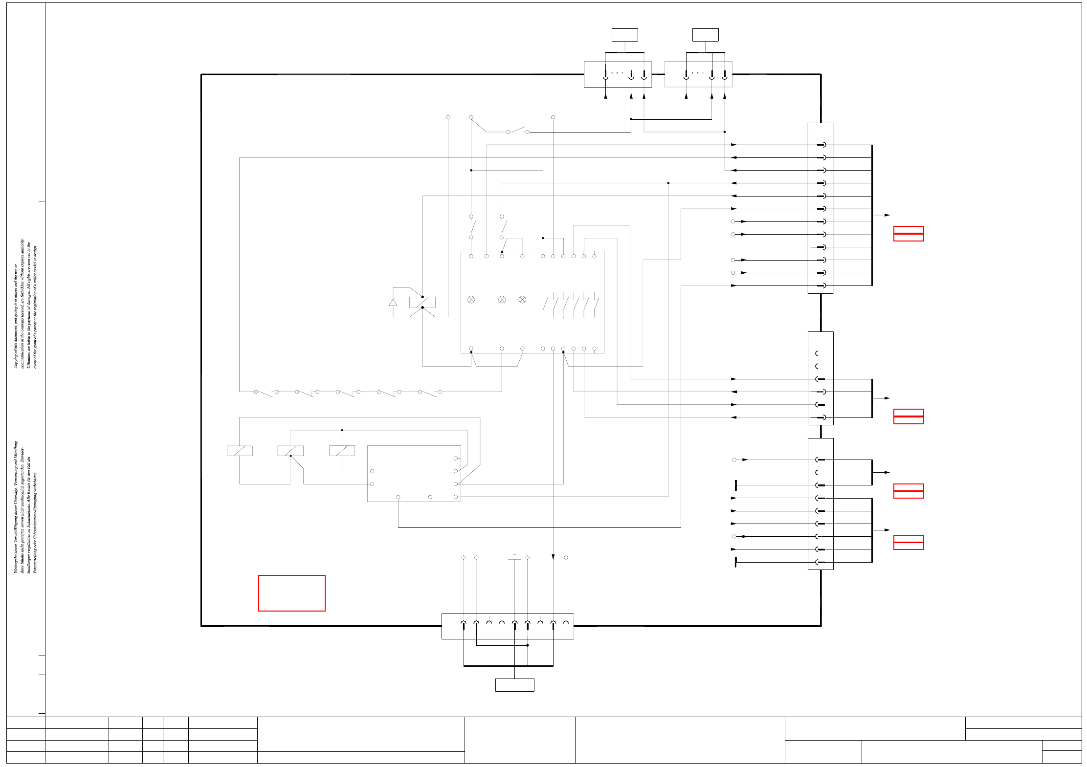
NH-070101LD3 Emergency stop loop, power supply (sh. 1 of 7)
X4L- X6
Channel1Power
supply
CSC K6
Channel2
42
K5
1
K5
3
GND(24)
X20:4
+24V
X20:3
K4.5
4
3
9
82
GND_P
GND_P
X16:11
X16:10
Voltage PCB_Mot(+)
Voltage PCB(+)
F8
+24V
GND (+5V)
GND (+24V)
Vin(-)Illumination
Vin(+)Illumination
F12
X16:8
4
3
2
1
2
7
8
9
6
5
(W5)
(W6)
(W5)
(W6)
(W6)
+5V
CSC54
CSC53
CSC44
Vin(-)Illumination
Vin(+)Illumination
n.u.
X16:7
F12
X18
1
2
1
4
3
1
2
(W6)
(W4)
(W4)
2
1
2
6
5
4
(W3)
(W3)
(W2)
(03046226)
To plug X3ra
sub-distributor
(sheet 6)
(sheet 5)
(03046225)
(03046225)
main distributor
To plug X3qa
(sheet 3)
(sheet 2)
03002506
To plug X3qa
main distributor
(sheet 2)
(sheet 3)
03002506
534333 6523
543424
44 66
ModifiedStatus Date
CAD file : NH-070101LD3_SH01.DWG
Orig./Repl.f./Repl.byStand.Name
Check.
Mat. no. :
Author Hi
Date
Sh.
Sh.
SIPLACE X-Series
1
7
Emergency-stop loop
Document st.
Product st.
Function st.
1. Hi
Hi1.
Hi7.
NH-070101LD3
10.07.06
10.07.06
10.07.06
11.01.2005
Copyright reserved
SIEMENS AG
Power supply
Voltage PCB(+)
13
14
To PCB conveyor, 00365546-W1
X15
31
X79
BK 2
4
3
GNYE
03002504
16
5
7
2
X7-10
X7-11
00354626
Power supply unit
A1(+)
A1(+)
K2
A2(-)
A2(-)
43
A1(+)
K4
K3
A2(-)
212 1
+24V2
n.u.
n.u.
GND(+24V2)
n.u.
Voltage PCB(-)
n.u.
EmergencyStopLoop1OK
X20:30
X20:40
U5(-)
servo
limiter,
Inrush current
ILS
X8-23 X8-20
X8-21
X7-13
X7-12
X8-19
6
1 5
EmergencyStopLoop1End
S_TapeCutter
S_XY
n.u.
Contactor relay blocks
K1.4 K2.4 K3.4
X5X3X1L+
A2 (-)
K4.4 K5
A1 (+)
V51
K5
CSC43
GND (+24V)
EmergencyStopLoop1OK
n.u.
n.u.
X20_4
13
2
X17
1
(W2)
12
11
2 (W2)
GY (W4)
+5V
n.u.
StartButtonOn
S_GantryCrash
EmergencyStopLoop1End
Software_CtrlOn
GND (+5V)
+24V
VoltageTapeCutter
X20_6
X20_3
X20_5
GN (W3)6
10
9
7
8
YE (W4)
1 (W2)
1 (W1)
2 (W1)
5
4
3
2
WH (W3)
BN (W3)
BN (W4)
GN (W4)
03009766 (W1+W2+W3)
X21
10
+34V
Servo Enable
03009786 (W1+W2+W3)
To axis unit 1
X13
1
X14
12
1
10
X31
S_Ready
To axis unit 2
12
X16
1WH (W4)
(03046225)
03002505
main distributor
To plug X2qa
(sheet 3)
(sheet 2)
See page 3-7