X4电路图.pdf - 第58页
2 - 3 NH-070 101LD3 Emerge ncy stop loo p, prot ective switch es CO trolle y docking unit, SIP LACE HF (sh. 3 of 7) Docume nt s t. Product st. Fun ction st. 1. Hi Hi 1. Hi 7. NH-0 7010 1LD 3 10.07.06 10.07.06 10.07.06 11…
2 - 2
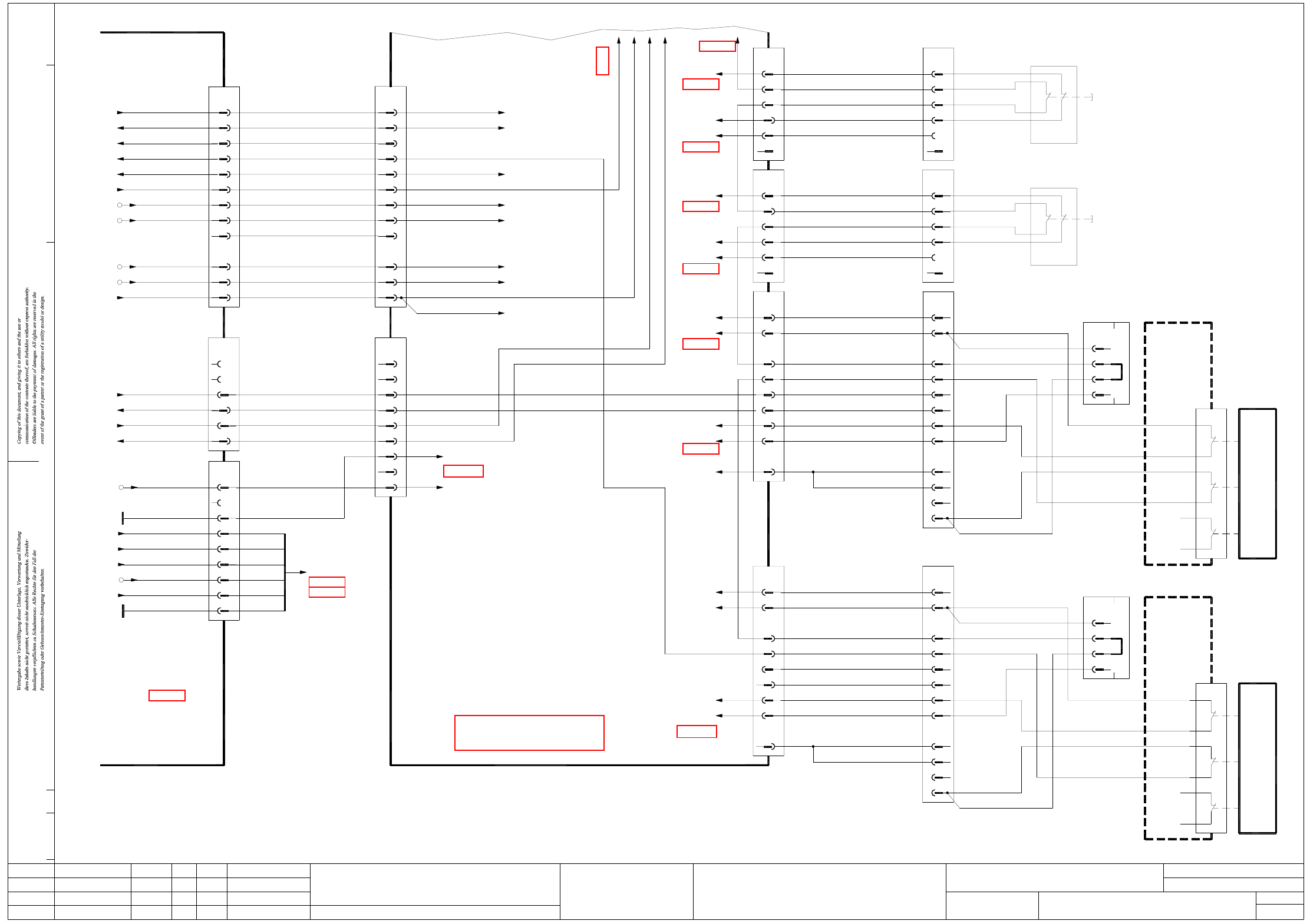
NH-070101LD3 Emergency stop loop, protective switches
CO trolley docking unit, SIPLACE X-series (sh. 2 of 7)
1
2
4
3
BK
BK
+24V
OG
BK
BU
GY+PK
WH+BN
GN+YE
Software_CtrlOn
EmergencyStopLoop1End
StartButtonOn
S_Ready
n.u.
3
4
5
BK
BK
2
1
BK
BK
X2qa
X4qb_2 (DI9)
X1qa_StartButton
CAN I/O module
X19qa_4
(sheet 4)
(sheet 4)
X1qa_0V
X1qa_24V
X73qa_9
(sheet 4)
X71qa_6
X72qa_4
X72qa_3
BK GY+PK
5
4
6
n.u.
GND
WH
BK
n.u.
BU
RD
1
2
3
OG
+24V
BK
(sheet 4)
X12qa_3
WH+BN
GN+YE
X13qa
SIPLACE X-Series, location 2
Component trolley
10 9
SIPLACE X-Series, location 3
Component trolley
12
n.u.
11
n.u.
11
10
(W1)gn
(W2)gn
n.u.
n.u.
32
31
22
(W1) (Cable)wh+24V
6
S_Flap
S_COTable3
10 9
7
8
EmergencyStopLoop1In
EmergencyStopLoop1Out
5
4
3
ye (W2)
n.u.
(W1)bn
n.u.
(W1)
n.u.
ye
(W2)
(W2)
bn
wh
GND
03002535
X133
1
2
n.u.
11
n.u.
12
11 10
03019057-W1/W2
n.u.
n.u.
(W1)
(W2)
gn
gn
n.u.
n.u.
X13f
Location 3
21
12
11
4
3
n.u.
2
1
n.u.
BK
SIPLACE X-Series
docking unit
Component trolley
S1
CO flap
03021042
Adapter connector
32
22
31
21
X53
03019057-W1/W2
n.u.
5
S_Flap
S_COTable2
ModifiedStatus Date
CAD file : NH-070101LD3_SH02.DWG
Orig./Repl.f./Repl.byStand.Name
Check.
Mat. no. :
Author Hi
Date
Sh.
Sh.
SIPLACE X-Series
2
7
Emergency-stop loop
Document st.
Product st.
Function st.
1. Hi
Hi1.
Hi7.
NH-070101LD3
10.07.06
10.07.06
10.07.06
11.01.2005
Copyright reserved
SIEMENS AG
Protective switch, component trolley, docking unit
SIPLACE X-Series
EmergencyStopLoopMTC2Out
EmergencyStopLoopMTC2In
S_EmergencyStopButtonMTC
X72qa_2_S_EmergencyStopButtonMTC BK 10+119
03002506
(W5)2Vin(-)Illumination 9
00354626
Power supply
(sheet 1)
GND_P
GND (+24V)
GND (+5V)
Vin(-)Illumination
Vin(+)Illumination
Vin(+)Illumination
X16:7
X16:11
F12
X16:8
X16:10
GND_P
F12
8
7
4
1
+24V 6
5
3
2
(W6)
(W5)
(W6)
(W6)
n.u.n.u.
2
3
+5V 4
2
1
11
X18
(W4)
(W6)
(W4)
03046225 (qa)
Main distributor
sub-distributor
X3ra
n.u.
9
8
GY
n.u.
X1qa_Vin(+) illumination
(sheet 4)
OG
X1qa_24V
X5qb_7 (DI22)
(sheet 4)
(sheet 4)
X1qa_M_Flap
76
7
8
9
n.u.
BK
BK
n.u.
10+11
9
8
3
5
4
n.u.
BK
BK
6
5
4
X1qa_0V
1
2
GND
+24V
WH
X23qa
2+3
GNYE+1
03002506
03002505
CSC53
CSC44
CSC54
CSC43
(W2)13
6 2
4
5
2
1
(W3)
(W2)
(W3)
n.u.
n.u.
2
n.u.
n.u.
1
X17
EmergencyStopLoop1OK
VoltageTapeCutter
GND (+5V)
GND (+24V)
X20:4
X20:3
X20:6
X20:5
GY (W4)12
11
10+24V
1 (W2)
2 (W2)
GN (W3)
YE (W4)
n.u. 9
8
+5V 7
6
2 (W1)
1 (W1)
S_Ready
StartButtonOn
S_GantryCrash
EmergencyStopLoop1End
Software_CtrlOn
WH (W4)
BN (W4)
GN (W4)
WH (W3)
BN (W3)
3
4
5
2
1
X16
X1qa_Software_CtrlOn
X14qa
CAN I/O module
CSC54
CSC53
CSC44
CSC43
BK3
7
6
WH
BK
4
5
BK
BK
n.u.
n.u.
2
1
n.u.
n.u.
X3qa
X1qa_0V
EmergencyStopLoop1OK
+24V
GND (+24V)
GND (+5V)
VoltageTapeCutter
12 BK
10
11
OG
WH
9
8
n.u.
WH
7
6
PK +5V
BK
X1qa_0V
X3qb_1 (DI0)
X1qa_24V
X1qa_0V
X1qa_5V
X1qa_0V
X5qb_3 (DI18)
(sheet 4)
(sheet 4)
X1qa_M_Flap
EmergencyStopLoopMTC2Out
EmergencyStopLoopMTC2In
X1qa_24V
BK
65
6
7
8
BK
BK
BK
9
8
7
3
2
4
BK
BK
+24V
OG
4
5
2+3
X24qa_4
(sheet 4)
(sheet 4)
X1qa_0V
X1qa_24V
1
6
5
GND
WH
GND
n.u.
WH
GNYE+1
X18qa
n.u.
RD
8
7
6
EmergencyStopLoop1Out
EmergencyStopLoop1In
+24V
3
4
2
n.u.
(W2)ye
(W1)
n.u.
bn
(W1)
(W2)
ye
bn
(W1)
(W2)wh
wh (Cable)
03002531
GND
GND
X123
1
n.u.
6
5
EmergencyStopLoop1In
EmergencyStopLoop1Out
S_Hood3
+24V
4
3
1
2
n.u.
n.u.
GY+PK
BU
WH+BN
GN+YE
22 12
21 11
03021042
Location 2
docking unit
SIPLACE X-Series
4
Component trolley
n.u.
12
11
2BK
3
1
X12f
n.u.
S1
CO flap
Adapter connector
Hood switch
Location 3
EmergencyStopLoop1Out
03002528-W1
S_Hood2
GND
n.u.
6
5
4
EmergencyStopLoop1In
+24V
03002527-W1
1
2
3
X52
GY+PK
03020409
n.u.
n.u.
BU
22 12
03020409
WH+BN
GN+YE
1121
Location 2
Hood switch
(sheet 5)
(sheet 6)
(sheet 4)
(sheet 4)
(sheet 4)
See page 4-9
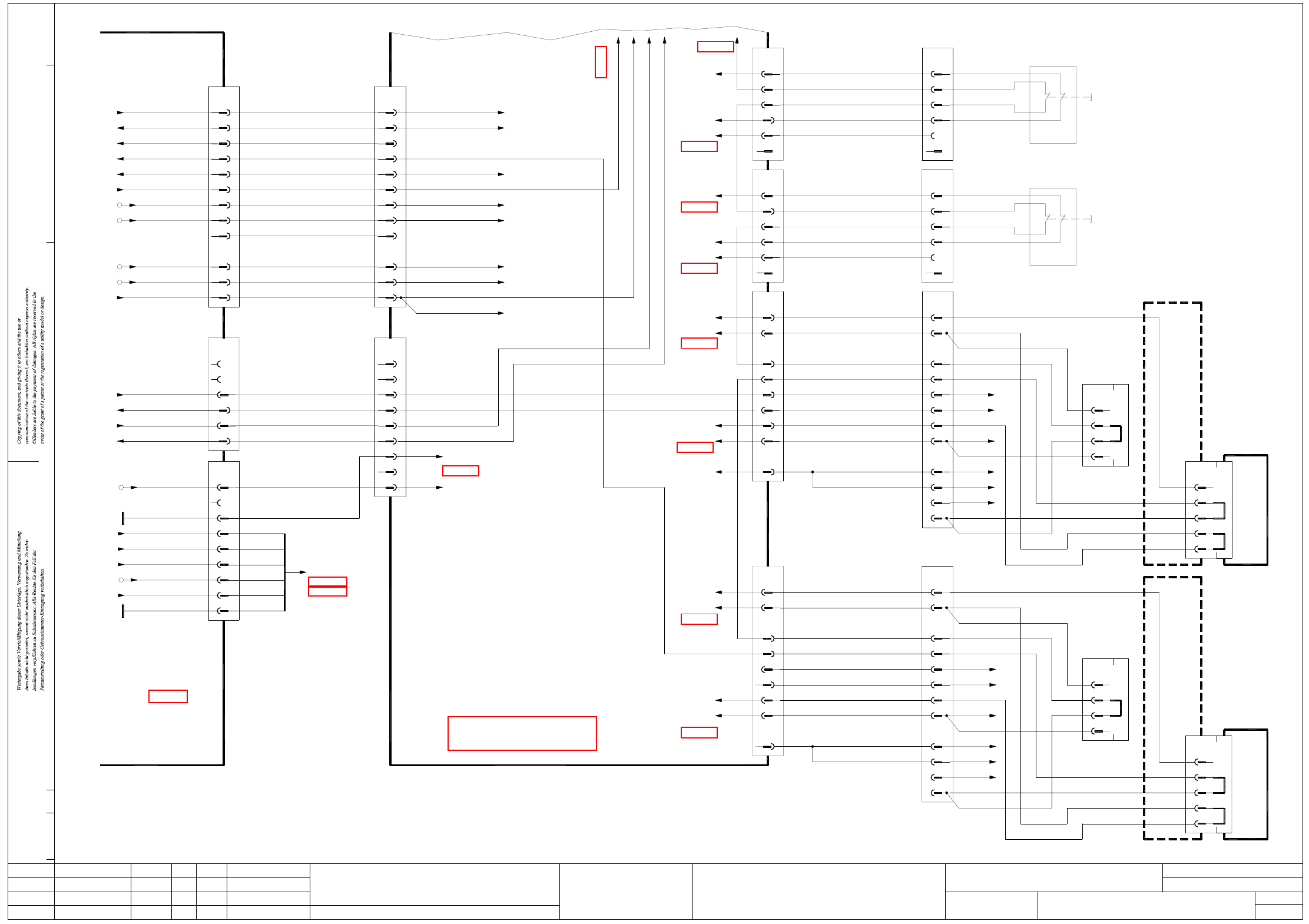
2 - 3
NH-070101LD3 Emergency stop loop, protective switches
CO trolley docking unit, SIPLACE HF (sh. 3 of 7)
Document st.
Product st.
Function st.
1. Hi
Hi1.
Hi7.
NH-070101LD3
10.07.06
10.07.06
10.07.06
11.01.2005
Copyright reserved
SIEMENS AG
Protective switch, component trolley, docking unit
SIPLACE HF
X72qa_2_S_EmergencyStopButtonMTC
EmergencyStopLoopMTC2Out
EmergencyStopLoopMTC2In
2Vin(-)Illumination 9
Power supply
GND_P
00354626
(sheet 1)
X16:7
X16:8
X16:10
X16:11
F12
GND_P
F12
GND (+24V)
GND (+5V)
+24V
Vin(+)Illumination
8
7
4
1
6
5
3
2
+5V
Vin(-)Illumination
Vin(+)Illumination
n.u.
2
3
4
2
1
X18
1 1
(sheet 4)
X1qa_Vin(+) illumination
(W5)
sub-distributor
(W6)
(W5)
(W6)
(W6)
(sheet 5)
X3ra
03002506
(W4)
(W6)
(W4) 9
8
GY
n.u.
03046225 (qa)
Main distributor
WH (W4)
BN (W4)
GN (W4)
WH (W3)
BN (W3)
GN (W3)
YE (W4)
GY (W4)
CSC43 13
CSC53
CSC44
CSC54
6 2
4
5
2
1
n.u.
n.u.
2
1
X17
EmergencyStopLoop1OK
X20:3
X20:4
X20:6
X20:5
+24V
GND (+24V)
12
10
11
+5V
n.u.
VoltageTapeCutter
GND (+5V)
9
ModifiedStatus Date
CAD file : NH-070101LD3_SH03.DWG
Orig./Repl.f./Repl.byStand.Name
Check.
Mat. no. :
Author Hi
Date
Sh.
Sh.
SIPLACE X-Series
3
7
Emergency-stop loop
2+3
(W1)2
6
10 9
7
8
5
4
3
(W1)6
(W1)8
(W2)
(W1)9
YE
(W1)7
(W1)
(W1)5
4
(W2)
(W2)BN
WH
X133
1
2
n.u.
n.u.
11
12
11 10
(W1)1
11 (W1)
(W2)
(W1)3
GN
(W1)
(W1)10
9
E29/30
C29/30
B28/30
D29/30
A29/30
Component trolley
SIPLACE HF, location 3
BK
RD
1
4
2
3
n.u.
BK
n.u.
CO flap
Adapter connector
03021042
X13f
Component trolley, docking unit
SIPLACE HF, location 3
X130
Component trolley
E29/30
D29/30
B29/30
C29/30
A29/30
X120
SIPLACE HF, location 2
RD
BK
03021020-W1/W2
X14qa X53
EmergencyStopLoopMTC2Out
EmergencyStopLoopMTC2In
S_COTable2
S_Flap
EmergencyStopLoop1Out
EmergencyStopLoop1In
+24V
03002531
GND
+24V
GND
S_Hood3
EmergencyStopLoop1In
EmergencyStopLoop1Out
X1qa_0V
3
2
5
6
7
8
4
BK
X5qb_3 (DI18)
(sheet 4)
X1qa_M_Flap
BK
BK
BK
(sheet 4)
X1qa_24V
BK
BK
+24V
OG
6
9
8
7
4
5
2+3
1
1
2
4
6
5
3
(sheet 4)
X1qa_0V
GND
WH
GND
n.u.
WH
X24qa_4
(sheet 4)
X1qa_24V
BK
BK
+24V
OG
BK
GNYE+1
X18qa
RD
WH+BN
GY+PK
GN+YE
BU
5
8
7
6
3
4
2
(W1)5
(W2)
(W1)
YE
8
(W1)
(W1)6
7
(W2)
(W1)4
BN
(W1)
(W2)WH
2
WH+BN
GN+YE
GY+PK
BU
n.u.
X123
1
6
5
4
3
1
2
(W1)1
22
21
03002528-W1
S_Hood2
EmergencyStopLoop1Out
EmergencyStopLoop1In
+24V
GND
03002527-W1
1
2
3
5
4
6
BK
X19qa_4
(sheet 4)
X1qa_0V
n.u.
GND
WH
BK
(sheet 4)
X1qa_24V
X72qa_4
OG
+24V
BK
(sheet 4)
X12qa_3
GY+PK
RD
BU
WH+BN
GN+YE
X13qa
WH+BN
BU
GY+PK
GN+YE
n.u.
6
5
4
1
2
3
X52
03020409
22
03020409
21
X12f
4
3
2
1
n.u.
n.u.
BK
03021042
CO flap
Adapter connector
SIPLACE HF, location 2
Component trolley, docking unit
Hood switch
Location 3
12
11
12
Location 2
Hood switch
11
(sheet 4)
(sheet 4)
(sheet 4)
(sheet 6)
n.u.
n.u.
n.u.
n.u.
n.u.
n.u.
n.u.
n.u. n.u.
n.u.
n.u.
n.u.
8
7
6
EmergencyStopLoop1End
S_Ready
StartButtonOn
S_GantryCrash
Software_CtrlOn
3
4
5
2
1
X16
X1qa_Software_CtrlOn
CSC54
CSC53
CSC44
CSC43
EmergencyStopLoop1OK
GND (+24V)
GND (+5V)
VoltageTapeCutter
X1qa_0V
(W2)
(W3)
(W2)
(W3)
03002506
BK3
7
6
4
5
WH
BK
BK
BK
2
1
X3qa
n.u.
n.u.
1 (W2)
2 (W2)
2 (W1)
1 (W1)
12
10
11
BK
+24VOG
WH
9
8
7
6
n.u.
WH
+5VPK
BK
CAN I/O module
X1qa_0V
X3qb_1 (DI0)
X1qa_24V
X1qa_0V
X1qa_5V
Software_CtrlOn
EmergencyStopLoop1End
StartButtonOn
03002505
3
4
5
2
1
n.u.
BK
BK
S_Ready
BK
BK
X2qa
X1qa_StartButton
CAN I/O module
X4qb_2 (DI9)
(sheet 4)
X71qa_6
X72qa_3
X73qa_9
10BK 10+1199
03021020-W1/W2
n.u.
n.u.
12
11
11 10
(W1)3
(W2)GN
(W1)
(W1)11
10
S_COTable3
S_EmergencyStopButtonMTC
S_Flap
EmergencyStopLoop1In
EmergencyStopLoop1Out
+24V
GND
03002535
OG
X1qa_24V
3
5
6
7
8
4
9
X5qb_7 (DI22)
(sheet 4)
X1qa_M_Flap
n.u.
BK
BK
n.u.
(sheet 4)
n.u.
BK
BK
7
10+11
8
9
6
5
4
1
2
X1qa_0V
GND
+24V
WH GNYE+1
X23qa
See page 4-9
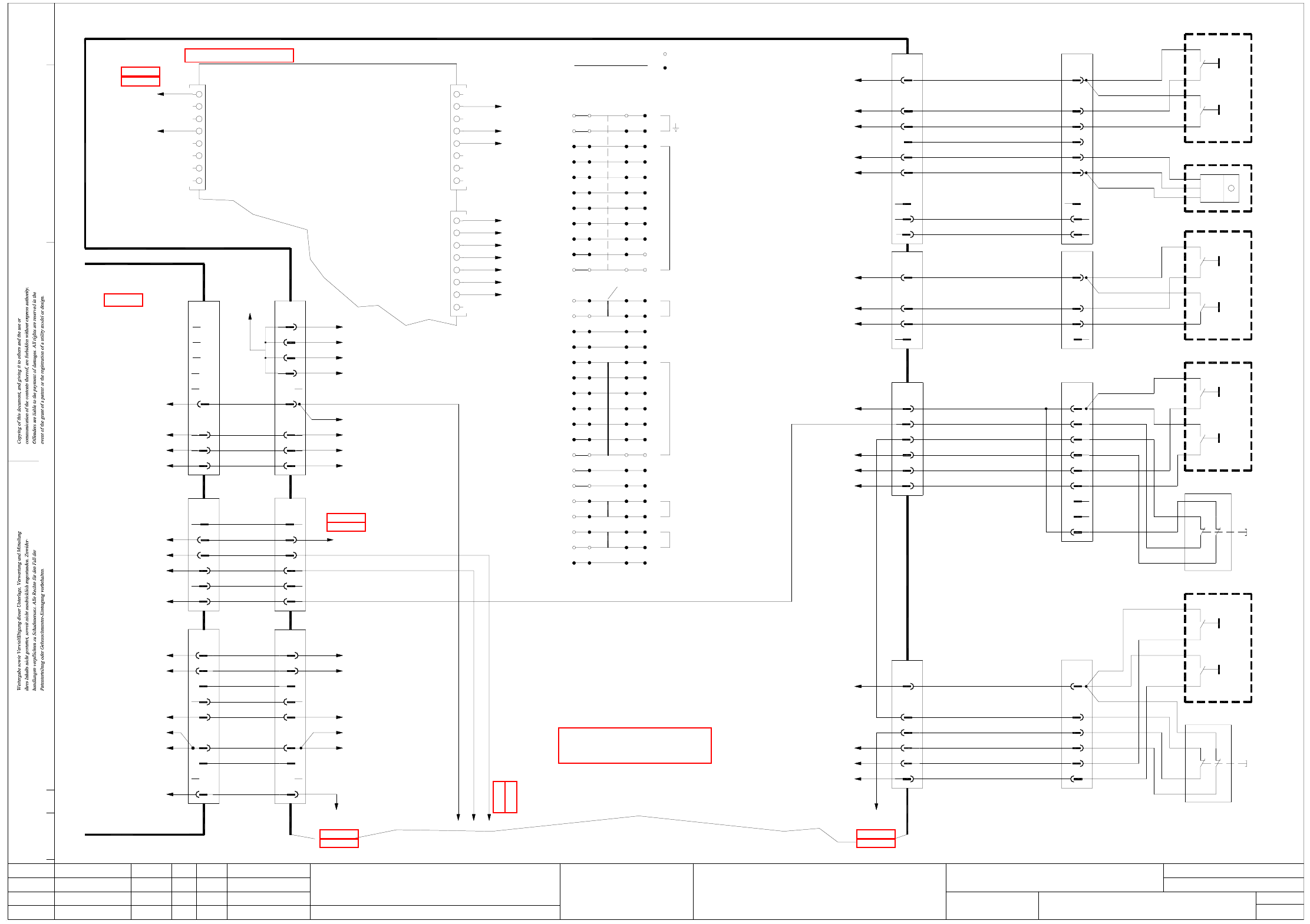
2 - 4
NH-070101LD3 Emergency stop loop, EMERGENCY STOP buttons,
START/STOP buttons, protective switches (sh. 4 of 7)
n.u.
7
BU
RD
03002524
S_StartButton
+24V
EARTHING
Terminal used
Terminal not used
X1qa_StartButton
X1qa_StopButton
X7qb_5(DO4)
X1qa_24V
BK
2
BN
n.u.
4
BK
WH
GND
6
5
BK
3
YE
GY
PK
GN
X9qa
OG
+24V 1
WH
S_StartButton
Ctrl_COCounter
S_StopButton
GND
03002523
+24V
CO counter
6
Pneumatic panel
YE
3
WH (W1)
X62
4
3
BN
RD
2
1
OG
BN
(W2)
(W2)
(W2)
(W1)
4
n.u.
03020410
S1
3
4
4
Stop
S2
Start
3
4
03004702
2
GN
WH
1
X57
BN
n.u.
n.u.
n.u.
8
9
7
BU
3
4
3
Stop
S2
Start
S1
5
1
Power supply panel
GN
2
n.u.
4
6
5
PK
GY
3
YE
WH
1
BN
X56
03004701
S2
4
Stop
4
3
3
Start
S1
(sheet 3) (sheet 3)
(sheet 3)
(sheet 2)
(sheet 3)
(sheet 3)
(sheet 2)
22
21
19
17
16
15
14
X18qa_7
DI23
DI22
BK
DI20
DI21
DI19
BK
BK
BK
X24qa_4
X23qa_7
X12qa_4
X11qa_4
DI17
DI18
DI16
BK
BK
OG
X19qa_4
X1qa_24V
12
11
10
Bridge
7
9
8
6
X7qb
A1 (qb)
Ctrl_CompressedAirPressure C&P/TWIN
2
Software_CtrlOn
Ctrl_ComponentCounter
5
n.u.
n.u.
6
7
n.u.
3
4
n.u.
1
X1qa
DO1
BK
BK
DO4
DO6
DO5
DO3
DO2
BK
X9qa_5
K2_A2
DO0
4
3
2
1
X1qa
Terminals overview
ab c d
PCB output, right-h. side
GN (W1)S_StartButtonBU
5
BK
5
X5qb_5 (DI20)
X1qa_StopButton
X1qa_StartButton
X13qa_2
(sheet 2)
BK
BK
6
5
RD
BU
S_StopButton
S_StartButton
X1qa_24V
Vin(+)Illumination (DC/DC converter)
StopButton
Flap
StartButton
Software_CtrlOn
X1qa_StopButton
X1qa_StartButton
S_Emerg.StopButtonPCBoutput
WH
+24V
OG
1
BK
2
BK
BK
4
3
BN+GN
YE+GY
PK
X12qa
+24V
EmergencyStopLoop1In
EmergencyStopLoop1Out
03002526
BK
6
RD S_StopButton
B1 WH
Emergency-stop
2111
6
5
VT
BK
12 22
S3
Cover flap, PCB conveyor
PCB output side, on the left
1
BN
YE+GY
PK+BU
2
4
3
RD
GN
X63
WH
Stop
4
4
3
3
S2
Start
S1
03020687
n.u.
7
9
8
n.u.
BK
6
YE
(W2)
(W1)
PCB output, right-h. side
22 12
21 11
X1qa_0V
+24V
-15V
+15V
X5qb_4 (DI19)
X1qa_24V
X1qa_StopButton
+5V
GND
X1qa_StartButton
X1qa_24V
BK S_StopButtonYE
3
X11qa
BK
BK
4
3
OG
BK
+24V
2
1
PK
YE+GY
WH
BN+GN
n.u.
4
S_HoodPCBoutput
EmergencyStopLoop1Out
EmergencyStopLoop1In
+24V
WH
03002525
X10qa
BK
2
OG
+24V 1
GN
WH+BN
8
n.u.
n.u.
9
Document st.
Product st.
Function st.
1. Hi
Hi1.
Hi7.
NH-070101LD3
10.07.06
10.07.06
10.07.06
11.01.2005
Copyright reserved
SIEMENS AG
Emergency-stop push-button, START buttons, STOP buttons
Protective switch
Main distributor
03046225 (qa)
WH
GND
X1qa_0V
WH
X1ra_0V
GN+YE (W3)
99
03002521
(W2)
(W2)
(W2)
(W1)
(W1)
(W1)
03002520
X24ra_7
X3rb_1
9
BK
n.u.
8
n.u.
7
RD
BU
X4ra_6
X1ra_StartButton
X1ra_StopButton
X1ra_Flap
GN
3
BK
5
BK
BK
6
4
n.u.
n.u.
GY
PK
YE
X73ra
BK
2
BK
1
BN
WH
X23ra_9
X23ra_5
X23ra_6
X23ra_4
BK BN
2
n.u.
BK
6
5
BK
3
BK
4
GN
BN
WH
GN
X72ra
1
n.u.
WH
X24qa_7
X2qa_6
EmergencyStopLoop1OK
X2qa_12
(sheet 2)
9
8
7
BK
n.u.
n.u.
(sheet 2)
X3qa_6
X3qa_5
X18qa_9 S_EmergencyStopButtonMTC
X4qa_6
X1qa_Flap
X1qa_StartButton
X1qa_StopButton
3
5
6
4
BK
BK
BK
n.u.
n.u.
2
1
X73qa
BK
BK
ModifiedStatus Date
CAD file : NH-070101LD3_SH04.DWG
Orig./Repl.f./Repl.byStand.Name
Check.
Mat. no. :
Author Hi
Date
Sh.
Sh.
SIPLACE X-Series
4
7
Emergency-stop loop
EmergencyStopLoopMTC4In
EmergencyStopLoopMTC4Out
EmergencyStopLoop1Input
BK
2
6
5
3
4
BK
n.u.
BK
BK
1
X72qa
n.u.
27
29
28
25
26
24
23
W1+W2
X4bm / X4cm
SST33
CAN I/O module
EmergencyStopLoop1OK
(W3)
(W3)
(W3)
03002519
DI7
1
X2rc_8(VIlluminationB)
X2rc_4(VIlluminationA)
X17ra_4
n.u.n.u.
GY
7
GY
8
BK
6
2
3
1
n.u.
3
n.u.
5
4
n.u.
2
n.u.
n.u.
n.u.
n.u.
n.u.
Sub-distributor
03046226 (ra)
(sheet 4)
X71ra
n.u.
8
X2qa_12
X1qa_Flap
DI1
2
n.u.
DI4
DI6
DI5
BK
DI3
DI2
5
n.u.
n.u.
n.u.
6
7
S_Flap
n.u.
3
4
BK
DI0
1
X3qb
5
DO7
X5qb
GNDWH
1
X1qa_0V
X1qa_24V
X2qc_8 (VLT33)
X1qa_0V
X2qc_7_VoltageIlluminationB
X2qc_9_VoltageIlluminationA
X17qa_4
Voltage tape cutter
n.u.
7
8
6
GY
GY
BK
BK
3
5
4
2
GY
WH
GND
OG
S_Emerg.StopButtonPCBoutput
X71qa
S_COTable2
3
S_HoodPCBoutput
S_COTable3
S_Hood3
6
n.u.
8
7
5
4
S_EmergencyStopLoop2OK
S_Hood2
2
1
n.u.
8
13
18
20
See page 4-9
See page 5-14