X4电路图.pdf - 第61页
2 - 6 NH-070 101LD3 Emerge ncy stop loo p, prot ective switch es CO trolle y docking unit, SIP LACE HF (sh. 6 of 7) 3 03002519 X71qa (sheet 4) main distributor (W3) GN+YE WH (W1) 1 2 3 1 (W3) 7 (W3) 8 9 (W3) 6 5 4 3 1 2 …
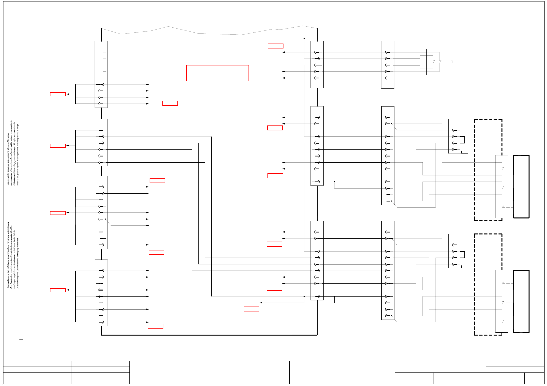
2 - 5
NH-070101LD3 Emergency stop loop, protective switches
CO trolley docking unit, SIPLACE X-series (sh. 5 of 7)
ModifiedStatus Date
CAD file : NH-070101LD3_SH05.DWG
Orig./Repl.f./Repl.byStand.Name
Check.
Mat. no. :
Author Hi
Date
Sh.
Sh.
SIPLACE X-Series
5
7
Emergency-stop loop
3
11
10 9
10
8
5
7
6
4
2
X113
1
n.u.
6
5
03002540
+24V
S_Hood4
EmergencyStopLoop1In
EmergencyStopLoop1Out
X14ra
BK
BK 4
BK
3
OG
1
2
X13ra_3
GN+YE
BU
GY+PK
WH+BN WH+BN
GN+YE
GY+PK
BU
X54
4
3
1
2
22
21
03020409
Hood switch
Location 4
22
n.u.
Component trolley
SIPLACE X-Series, Location 1
(W1)GN
GN (W2)
n.u.
n.u.
n.u.
n.u.
n.u.
YE
BN
YE
(W2)
(W1)
(W1)
n.u.
WH
WH
BN
GN
GN
03019057-W1/W2
(W2)
(W2)
(W1)
(W1)
(W2)
31
Component trolley
SIPLACE X-Series, Location 4
32
docking unit
Location 4
SIPLACE X-Series
Component trolley
4
3
22
21
12
11
S1
CO flap
Adapter connector
03021042
X14f
2
1
32
31
BN (W2)
n.u.
n.u.
n.u.
n.u.
YE
BN
YE
(W2)
(W1)
(W1)
WH
WH
n.u.
03019057-W1/W2
(W2)
(W1)
Location 1
docking unit
SIPLACE X-Series
2
Component trolley
4
3
21
12
11
S1
Adapter connector
03021042
X11f
1
CO flap
n.u.
BK
n.u.
n.u.
BK
n.u.
(sheet 7)
Document st.
Product st.
Function st.
1. Hi
Hi1.
Hi7.
NH-070101LD3
10.07.06
10.07.06
10.07.06
11.01.2005
Copyright reserved
SIEMENS AG
Protective switch, component trolley, docking unit
SIPLACE X-Series
(sheet 7)
X5rb_7 (DI22)
X5rb_3 (DI18)
X24ra_4
(sheet 7)
(sheet 7)
(sheet 7)
(sheet 7)
X1ra_Flap
X1ra_Flap
X1ra_0V
X1ra_24V
X1ra_24V
X1ra_0V
X1ra_0V
X1ra_24V
X1ra_StopButton
X3ra
8
1 (W5) 9
(sheet 1)
X18
power supply
03002506
3
2
4
3
(W5) 7
6
(W6)
(W6)
5
4
1
2
(W6) 1
(W6) 2
(sheet 4)
03002521
X73qa
main distributor
RD
9
BU
7
8
PK
GY
6
5
YE
GN
4
3
Vin(+)IlluminationGY
n.u.
X1ra_Vin(+)Illumination
(sheet 7)
n.u.
Vin(-)Illumination
GND24V
WH
n.u.
WH
OG +24V
GND5V
+5VPK
WH
X1ra_0V
X1ra_24V
X1ra_0V
X1ra_0V
X1ra_5V
EmergencyStopLoop1OK
n.u.
BK
n.u.
S_ControlOnBK
BK S_Flap
n.u.
n.u.
CAN I/O module
X3rb_1(DI0)
X24ra_7
X4ra_6
X1ra_Flap
(sheet 7)
CAN I/O module
X4rb_8(DI15)
X71ra
X72ra
X73ra
BN (W1)
2
main distributor
X72qa
03002520
(sheet 4)
WH
BN
1
2
WH
GN
BN
GN
(W2)
4
(W2)
(W2)
6
5
(W1)
3
03002519
X71qa
(sheet 4)
main distributor
(W3)GN+YE
WH (W1)
1
2
3
1
(W3)
7
(W3)
8
9
(W3)
6
5
4
3
1
2
03046226 (ra)
BK S_EmergencyStopButtonMTC
EmergencyStopLoop1Input
EmergencyStopLoopMTC4In
EmergencyStopLoopMTC4Out
S_StopButton
S_StartButtonBK
BK
BK
n.u.
BK
BK
X1ra_StartButton
(sheet 7)
WH
n.u.
VoltageTapeCutter
VoltageIlluminationA
VoltageIlluminationB
GY
GY
GND
BK
n.u.
(sheet 7)
X1ra_0V
(VillB)
(VillA)
X2rc_8
X2rc_4
X17ra_4
n.u.
n.u.
n.u.
n.u.
Sub-distributor
n.u.
11
12
n.u.
S_EmergencyStopButtonMTC
EmergencyStopLoopMTC4Out
EmergencyStopLoopMTC4In
S_COtable4
S_Flap
EmergencyStopLoop1In
EmergencyStopLoop1Out
+24V
GND
03002547
BK
BK
9
BK
6
BK 7
8
BK
5
BK
4
10+11
7
9
8
6
5
X23ra
BK
3
WH
1
OG
2
GNYE+1
4
2+3
n.u.
11
10
11
10
9
6
7
8
5
4
X143
3
1
2
n.u.
12
12
11
S_COtable1
S_Flap
EmergencyStopLoop1out
EmergencyStopLoop1in
+24V
03002542
GND
GND
BK
43
9
n.u.
BK
8
n.u.
5
n.u.
BK 7
6
BK
4
10+11
9
6
8
7
5
X18ra
OG
2
WH
1
WH
6
n.u.
5
GNYE+1
2+3
RD
See page 4-10
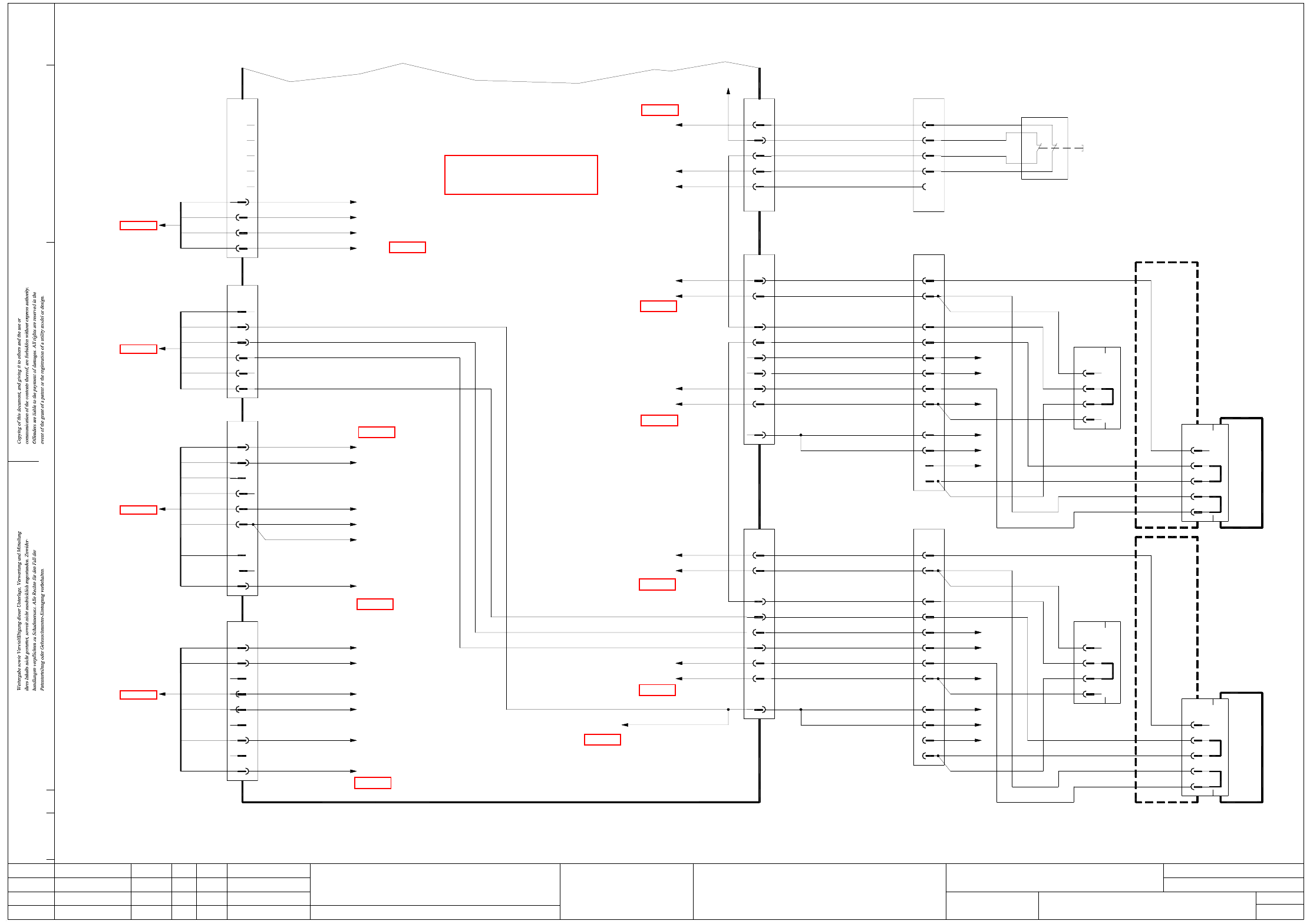
2 - 6
NH-070101LD3 Emergency stop loop, protective switches
CO trolley docking unit, SIPLACE HF (sh. 6 of 7)
3
03002519
X71qa
(sheet 4)
main distributor
(W3)GN+YE
WH (W1)
1
2
3
1
(W3)
7
(W3)
8
9
(W3)
6
5
4
3
1
2
03046226 (ra)
BK S_EmergencyStopButtonMTC
EmergencyStopLoop1Input
EmergencyStopLoopMTC4In
EmergencyStopLoopMTC4Out
S_StopButton
S_StartButtonBK
BK
BK
n.u.
BK
BK
X1ra_StartButton
(sheet 7)
WH
n.u.
VoltageTapeCutter
VoltageIlluminationA
VoltageIlluminationB
GY
GY
GND
BK
n.u.
(sheet 7)
X1ra_0V
(VillB)
(VillA)
X2rc_8
X2rc_4
X17ra_4
n.u.
n.u.
n.u.
n.u.
Sub-distributor
Component trolley
SIPLACE HF, location 1
RDD29/30
11 (W1)
n.u.
11
03021020-W1/W2
(W1)3
12
GN
n.u.
(W2)
S_EmergencyStopButtonMTC
EmergencyStopLoopMTC4Out
EmergencyStopLoopMTC4In
S_COtable4
S_Flap
EmergencyStopLoop1In
EmergencyStopLoop1Out
+24V
GND
03002547
BK
BK
9
BK
6
BK 7
8
BK
5
BK
4
10+11
7
9
8
6
5
X23ra
BK
3
WH
1
OG
2
GNYE+1
4
2+3
YE
8
n.u.
11
10
11
10
11
10
9
9
6
6
7
8
7
5
4
5
4
(W1)
(W1)
(W1)
(W1)
(W2)
(W1)
(W1)
(W1)
(W1)
WH
BN
GN
X143
3
1
2
1
2
n.u.
12
3
(W2)
(W2)
(W1)
(W1)
(W1)
(W2)
C29/30
Component trolley
SIPLACE HF, location 4
B29/30
E29/30
BK
Component trolley, docking unit
Adapter connector
n.u.
4
BK
n.u.
03021042
1
2
3
X14f
A29/30
D29/30
X140
RD
SIPLACE HF, location 4
CO flap
E29/30
C29/30
B29/30
BK
03021020-W1/W2
12
11
S_COtable1
S_Flap
EmergencyStopLoop1out
EmergencyStopLoop1in
+24V
03002542
GND
GND
BK
43
9
n.u.
BK
8
n.u.
5
n.u.
BK 7
6
BK
4
10+11
9
6
8
7
5
X18ra
OG
2
WH
1
WH
6
n.u.
5
GNYE+1
2+3
RD
BN (W2)
3
YE
11
10
9
9
10
10
8
8
5
5
7
6
7
6
4
4
(W1)
(W1)
(W2)
(W1)
(W1)
(W1)
(W1)
(W1)
WH
2
2
X113
1
1
n.u.
6
5
(W2)
(W1)
(W1)
03002540
+24V
S_Hood4
EmergencyStopLoop1In
EmergencyStopLoop1Out
X14ra
BK
BK 4
BK
3
OG
1
2
X13ra_3
GN+YE
BU
GY+PK
WH+BN WH+BN
GN+YE
GY+PK
BU
X54
4
3
1
2
22
21
03020409
CO flap
Component trolley, docking unit
n.u.
4
3
n.u.
03021042
Adapter connector
BK
X11f
2
1
A29/30
X110
SIPLACE HF, location 1
Hood switch
Location 4
(sheet 7)
Document st.
Product st.
Function st.
1. Hi
Hi1.
Hi7.
NH-070101LD3
10.07.06
10.07.06
10.07.06
11.01.2005
Copyright reserved
SIEMENS AG
Protective switch, component trolley, docking unit
SIPLACE HF
(sheet 7)
X5rb_7 (DI22)
X5rb_3 (DI18)
X24ra_4
(sheet 7)
(sheet 7)
(sheet 7)
(sheet 7)
X1ra_Flap
X1ra_Flap
X1ra_0V
X1ra_24V
X1ra_24V
X1ra_0V
X1ra_0V
X1ra_24V
X1ra_StopButton
X3ra
8
1 (W5) 9
(sheet 1)
X18
power supply
03002506
3
2
4
3
(W5) 7
6
(W6)
(W6)
5
4
1
2
(W6) 1
(W6) 2
(sheet 4)
03002521
X73qa
main distributor
RD
9
BU
7
8
PK
GY
6
5
YE
GN
4
3
Vin(+)IlluminationGY
n.u.
X1ra_Vin(+)Illumination
(sheet 7)
n.u.
Vin(-)Illumination
GND24V
WH
n.u.
WH
OG +24V
GND5V
+5VPK
WH
X1ra_0V
X1ra_24V
X1ra_0V
X1ra_0V
X1ra_5V
EmergencyStopLoop1OK
n.u.
BK
n.u.
S_ControlOnBK
BK S_Flap
n.u.
n.u.
CAN I/O module
X3rb_1(DI0)
X24ra_7
X4ra_6
X1ra_Flap
(sheet 7)
CAN I/O module
X4rb_8(DI15)
X71ra
X72ra
X73ra
BN (W1)
2
main distributor
X72qa
03002520
(sheet 4)
WH
BN
1
2
WH
GN
BN
GN
(W2)
4
(W2)
(W2)
6
5
(W1)
ModifiedStatus Date
CAD file : NH-070101LD3_SH06.DWG
Orig./Repl.f./Repl.byStand.Name
Check.
Mat. no. :
Author Hi
Date
Sh.
Sh.
SIPLACE X-Series
6
7
Emergency-stop loop
See page 4-10
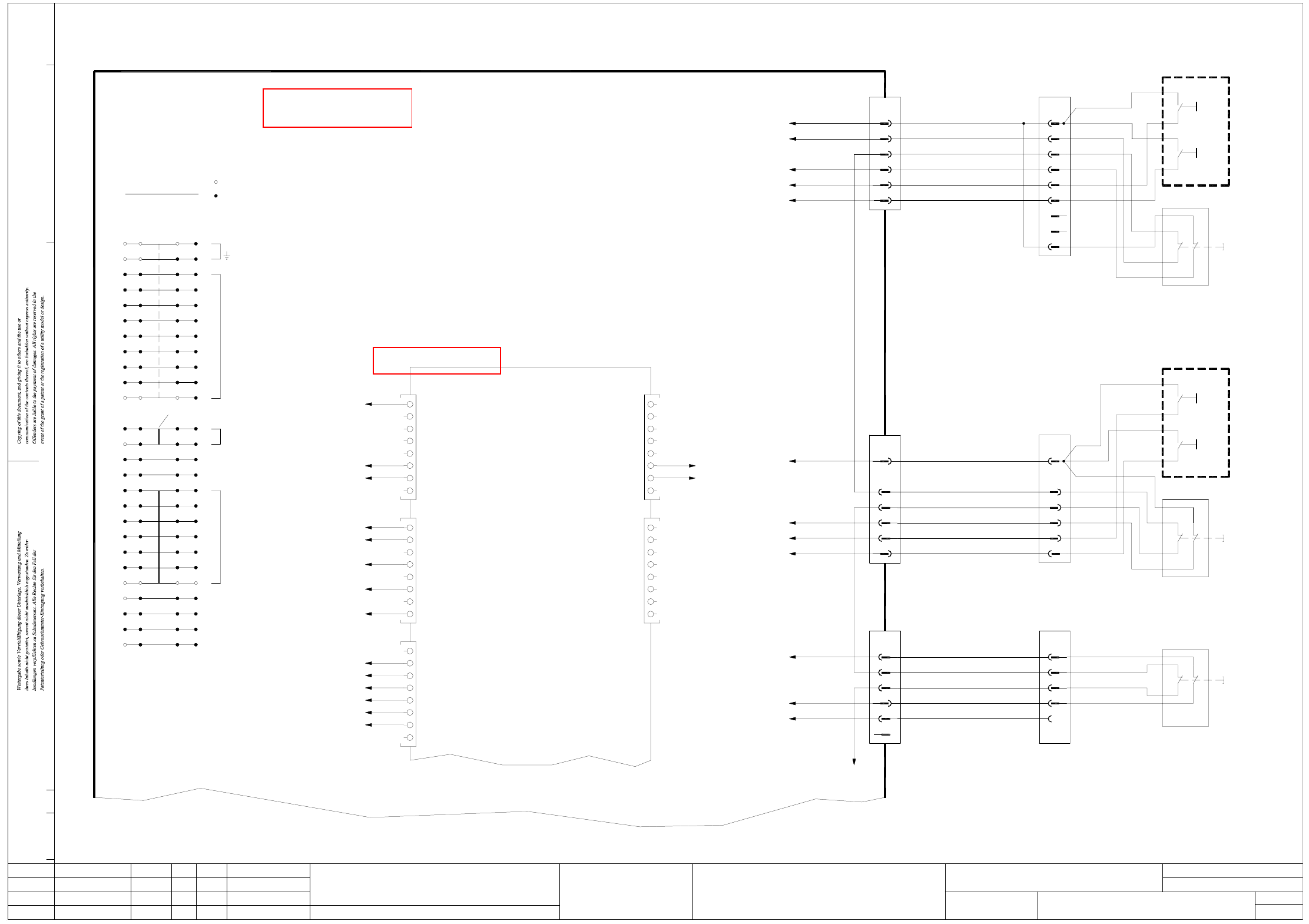
2 - 7
NH-070101LD3 Emergency stop loop, EMERGENCY STOP buttons,
START/STOP buttons, protective switches (sh. 7 of 7)
BK
BK
n.u.
2
1
X5rb
8
X1ra_24V
X4ra_6
X4ra_4
X1ra_StartButton
X1ra_StopButton
BK
DI9
DI10
DI12
DI11
DI13
DI14
n.u.
BK
n.u.
n.u.
BK
n.u.
6
5
n.u.
3
4
2
DI8
DI6
DI7
BK
OG
X4rb
1
n.u.
7
8
6
7
n.u.
n.u.
8
Ctrl_CompressedAirMainValve
n.u.
n.u.
n.u.
6
5
n.u.
n.u.
3
4
2
Ctrl_VacuumPumpOn
n.u.
X8rb
1
n.u.
7
8
6
Terminal not used
Terminal used
EARTHING
6
12
13
11
8
10
9
7
Bridge
+5V
GND
Terminals overview
1
5
4
3
2
ba
ModifiedStatus Date
CAD file : NH-070101LD3_SH07.DWG
Orig./Repl.f./Repl.byStand.Name
Check.
Mat. no. :
Author Hi
Date
Sh.
Sh.
SIPLACE X-Series
7
7
Emergency-stop loop
Document st.
Product st.
Function st.
1. Hi
Hi1.
Hi7.
NH-070101LD3
10.07.06
10.07.06
10.07.06
11.01.2005
Copyright reserved
SIEMENS AG
Emergency-stop push-button, START buttons, STOP buttons
Protective switch
Emergency-stop loop start
+15V
14
X20ra_2
BK
DI5
StartButton
StopButton
Vin(+)Illumination (DC/DC converter)
26
25
24
Flap
19
21
23
22
20
18
17
16
15
+24V
-15V
S_Hood1
S_COtable1
S_Hood4
S_COtable4
S_HoodPCBinput
S_EmergencyStopButtonPCBinput
S_VacuumPumpOn
S_PressureSensorMainValve
S_GantryCrash2
S_StartButton
S_EmergencyStopButtonMTC
S_ControlON
S_StopButton
BK
7
n.u.
X23ra_9
X18ra_7
X19ra_4
X12ra_4
X24ra_4
X23ra_7
X11ra_4
3
D19
D21
D20
D22
D23
n.u.
BK
BK
BK
BK
6
n.u.
8
7
5
4
D16
D18
D17
DI15
21
X61
X64
55
OG
DO2
DO4
DO3
DO1
DO0
X1ra_StopButton
X1ra_StartButton
WH
X12ra
1
03002538
+24V
1
S_StartButton
S_StopButton
BU
RD
BK
6
BK
7
WHB1
9
8
6
X5rb_4 (DI19)
X1ra_24V
X1ra_24V
+24V
S_HoodPCBinput
EmergencyStopLoop1Out
EmergencyStopLoop1In
X11ra
WH
PK
BN+GN
YE+GY
BK
4
BK
3
OG
OG
2
1
+24V
4
3
WH
2
1
03002537
WH
BN
03020687
S1
Start
Stop
3
S2
4
3
n.u.
BK
n.u.
(W2)
YE
GN
(W1)
(W1)
PCB input, left-h. side
Cover flap, PCB conveyor
22 12
21 11
WH (W1)
RD
BN (W2)
(W2)
BN
OG
(W1)
(W2)
03020410
S1
PCB input, left-h. side
Start
Stop
3
4
S2
4
3
X1ra
dc
CAN I/O module
EmergencyStopLoop1OK
X73ra_9
X3rb
DI4
DI3
DI2
DI1
DI0
n.u.
n.u.
n.u.
n.u.
BK
3
n.u.
n.u.
n.u.
4
5
n.u.
1
2
X7rb
3
n.u.
n.u.
n.u.
4
5
n.u.
n.u.
1
2
A1 (rb)
Sub-distributor
03046226 (ra)
K1_A1
BK
DO5
PCB input side on the right
X1ra_24V
4
X51
X14ra_2
WH
n.u.
BK
BK
BK
BK
BK
X1ra_24V
DO15
X1ra_0V
X19ra_4
X5rb_5 (DI20)
X1ra_StopButton
X1ra_StartButton
DO9
DO13
DO14
DO12
DO10
DO11
K2_A1
DO8
BK
DO7
DO6
EmergencyStopLoop1In
EmergencyStopLoop1Out
3
BU
RD
GY+PK
5
6
BK
4
BK
GN+YE
WH+BN
X13ra
BK
2
OG
1
3
GND
S_Hood1
5
n.u.
6
4
+24V
03002539
2
1
S_StopButton
S_StartButton
S_EmergencyStopButtonPCBinput
EmergencyStopLoop1In
EmergencyStopLoop1Out
BU
5
RD
6
YE+GY
BN+GN
PK
3
4
2
5
6
3
4
2
GY+PK
BU
GN+YE
WH+BN
03020409
Location 1
Hood switch
22 12
21 11
BK
VT
PK+BU
RD
GN
YE+GY
EMERGENCY STOP
12 22
S3
11
See page 4-10
See page 5-14