YS24 保养手册.pdf - 第21页
3-19 3 Periodic maintenance items 6 Remo ve the cap bolt for spline shaft cleaning. Use the precision wrench (supplied) t o remove the cap bolt (hex head bolt). 53321-L2-00 c …
3-18
3
Periodic maintenance items
3.2 Cleaning and lubricating the inside of the spline shaft
Dust or grime may adhere to the air path of spline shafts and cause component pickup or mounting errors.
Although depending on the air supply condition and operating time, the inside of each spline shaft should be
cleaned once every 3 months.
c
3.2.1 Cleaning the inside of the spline shaft
e
1
Make the preparations for the
cleaning and lubricating work.
1. Take off all accessories susceptible to the
magnetic fields, such as a wristwatch
and/or magnetic ID card.
2. Press the emergency stop button to put
the machine in the emergency stop
state.
3. Put square bandages on the Y-axis linear
guide and push-up plate.
4. Move the head to a convenient position
for maintenance work.
n
NOTE
Move the scan camera to the right or left away from
the head assembly so that the scan camera will not get
dirty.
2
Remove the nozzles from all heads.
Remove all nozzles by hand.
TIP
When the machine is equipped with a nozzle station
(option), press the [Nozzle Change] button on the
[Unit]-[Head] tab screen to retract all nozzles.
3
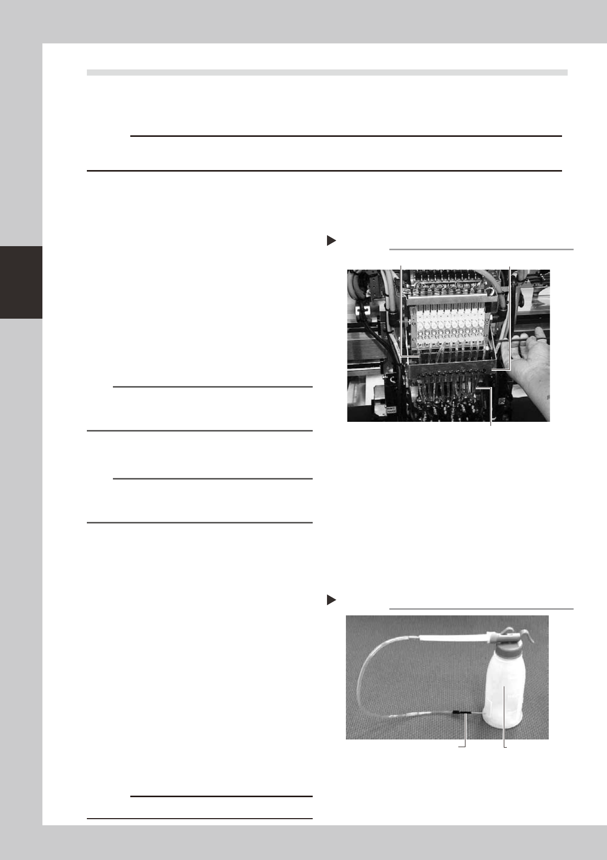
Disconnect the air hose from each
spline shaft.
Disconnect all air hoses which have been
inserted into the ejector side (upper) and
spline side (lower) of each head.
53318-L2-00
4
Remove the air hose bracket.
Remove the bolts (2 pcs.) securing the air
hose bracket with the hex wrench or
T-handle hex wrench. After that, remove the
air hose bracket completely.
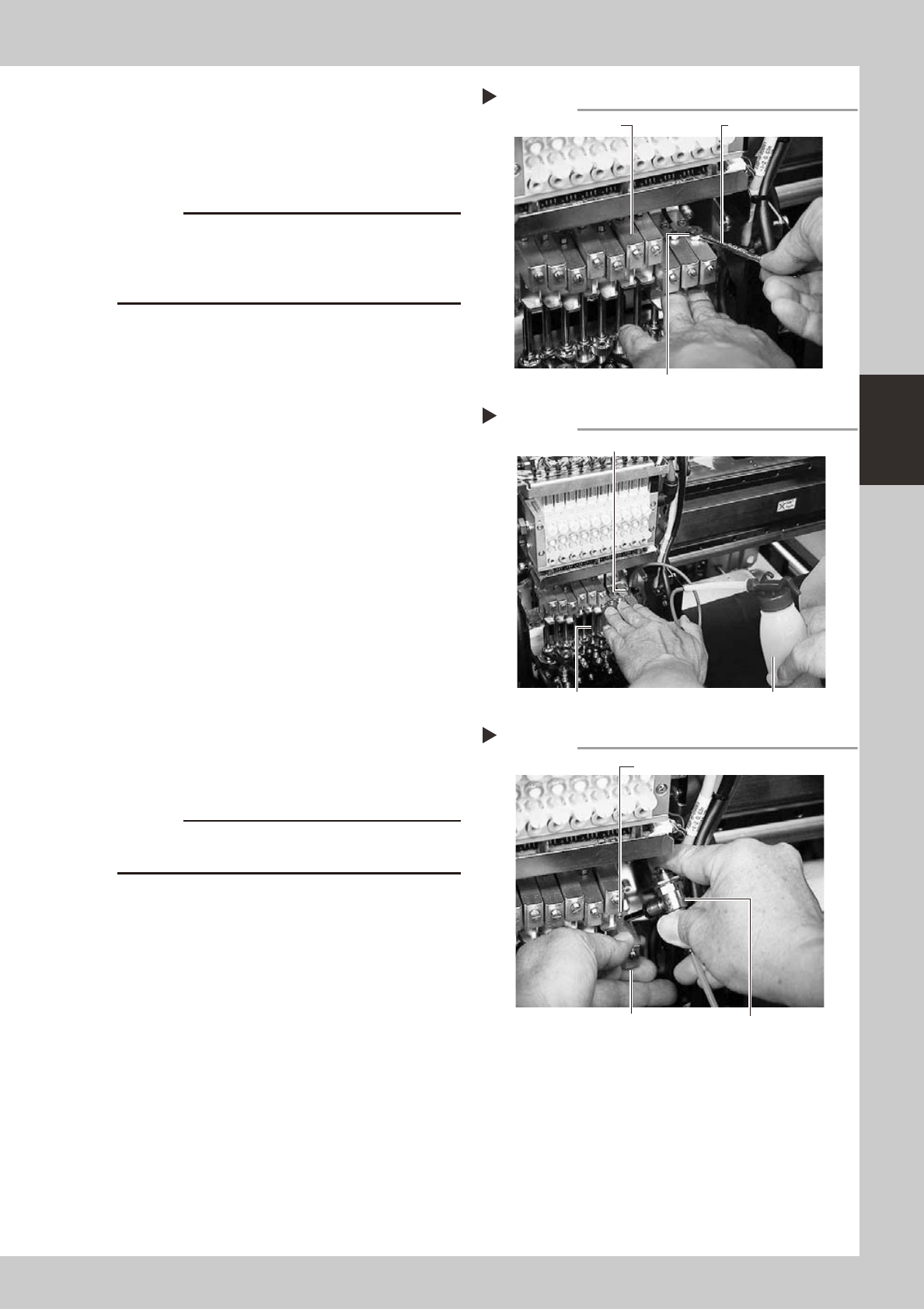
5
Prepare the cleaning kit (KHN-
M8860-00X).
1. Pour IPA (isopropyl alcohol) into the
container of the cleaning kit.
2. Place a shop cloth or rag under the
spline shaft to be cleaned.
53319-L2-00
c
Disconnecting the air hoses
Step 3, 4
Air hose (spline side)
Air hose bracket
Air hose (ejector side)
Cleaning kit
Step 5
Pump (IPA container)
Nozzle
3-19
3
Periodic maintenance items
6
Remove the cap bolt for spline
shaft cleaning.
Use the precision wrench (supplied) to
remove the cap bolt (hex head bolt).
53321-L2-00
c
not to drop it.
a new one.
7
Clean the inside of the spline shaft.
1. Insert the nozzle of the cleaning kit into
the cleaning hole of the spline shaft.
2. Pour alcohol (IPA) into the spline shaft air
path to clean away dust and grime.
53322-L2-00
8
Blow air into the spline air path.
1. Prepare an air blow tool (available as
option) and connect it to an air
connector on a nearby machine. Then
insert the air blow tool nozzle into the air
joint of the spline shaft.
2. Place a shop cloth under the lower end
of the spline shaft, and blow air through
the spline shaft while blocking the lower
hole with your finger.
3. Repeat steps 7 and 8 until the IPA flowing
out from the spline shaft becomes clean.
Make sure that after blowing air, smear
no longer appears on the shop cloth
placed under the lower end of the spline
shaft, and then reattach the cap bolt.
53334-L2-00
c
to wear safety goggles.
9
Repeat the cleaning procedure.
Repeat steps 6 to 8 to clean the inside of
the spline shafts of all heads.
0
Reinstall the air hose and nozzle
back to their original positions.
Removing the cap bolt
Step 6
Precision wrench (supplied)
Cap bolt
Upper block of spline shaft
Cleaning the spline shaft
Step 7
Nozzle of cleaning kit
Spline shaft Pump of cleaning kit
Air blow into spline shaft
Step 8
Blow the air from this hole.
Air blow tool
Block the lower hole with your finger.
3-20
3
Periodic maintenance items
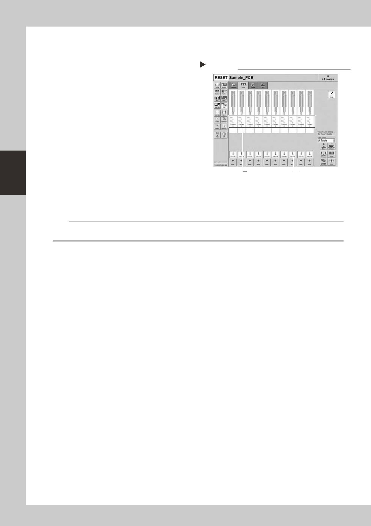
3.2.2 Checking the negative pressure
After cleaning the spline shafts, check the negative pressure (vacuum level) generated in each head.
1
After assembly, check the vacuum
levels.
1. Leave nozzles detached from the heads.
2. Open the [Unit]-[Head] tab screen and
press the [Vacuum] button to generate a
negative pressure. Read the "Max" values
shown on the screen and determine
whether the vacuum levels are
appropriate by referring to the criteria
below.
54311-L2-00
2
Reattach the nozzles.
Attach the nozzles by hand back to the
heads.
n
Vacuum level criteria in spline air path
When nozzle is open : 70 or less
When nozzle is sealed : 190 or more
n
NOTE
The vacuum level in the spline shaft air path might sometimes differ slightly depending on the air source and operating
conditions. Use the above criteria for reference during maintenance.
Checking the vacuum level
Step 1
[Vacuum] button
Read "Max" values.