Process Lens PL Service Manual_EN.pdf - 第106页
3 Replacing spare parts 10 6 Se rv ic e Ma nu al P ro ce ss L en s PL - 0 3/ 20 25 Replacing laser light barrier cables and fiber optic cables Parts Fig.144: Laser light barriers and fiber optic cables 1 03092408-xx Fib…
3 Replacing spare parts
Service Manual Process Lens PL - 03/2025 105
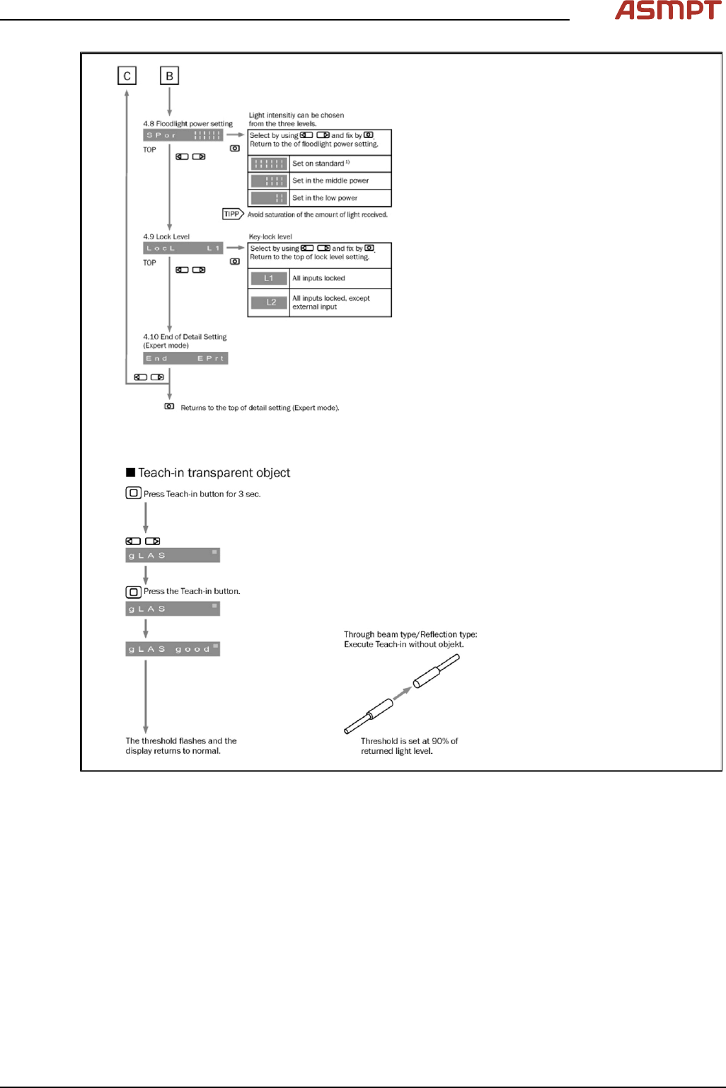
Fig.143: Setting the fiber optic sensor - 4
3 Replacing spare parts
106 Service Manual Process Lens PL - 03/2025
Replacing laser light barrier cables and fiber optic cables
Parts
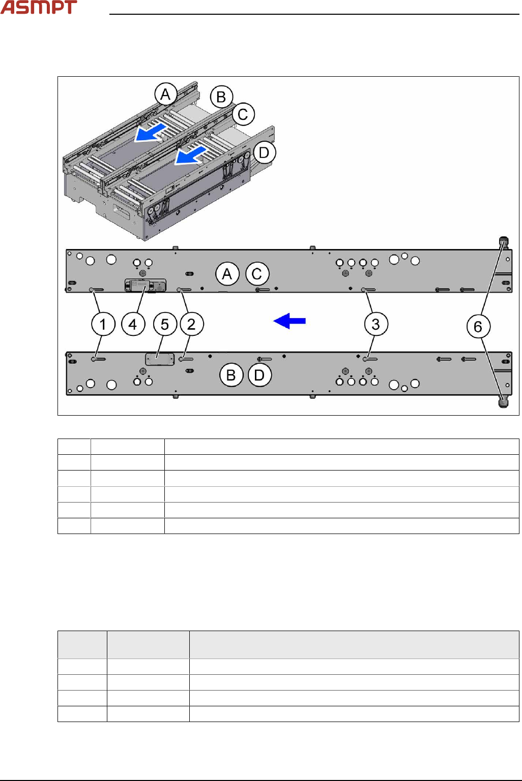
Fig.144: Laser light barriers and fiber optic cables
1 03092408-xx Fiber optic cable LL3-TV05 3m
2 03092408-xx Fiber optic cable LL3-TV05 3m
3 03092407-xx Fiber optic cable LL3-TV05 2m
4 03098280‑xx Laser light barrier transmitter*
5 03098281‑xx Laser light barrier receiver*
6 Cable outlet on the input side of the rail
* See also 3.5.1.6.1 "Replacing the laser light barrier for the transmitter/receiver" [}92]
The fiber optic cables are routed through the conveyor rail to the cable outlet(6). From there, the fiber
optic cables are routed under the lifting table to the fiber optic sensors.
The laser light barrier cables are routed through the conveyor rail to the cable outlet(6). From there,
the cables are routed under the lifting table to the conveyor control.
Laser light barrier cable transmitter and receiver
Side
panel
Item no. Designation
A 03113845-xx Cable PCB centering laser LLBt1 panel-A
B 03113846-xx Cable PCB centering laser LLBt1 panel-B
C 03113847-xx Cable PCB centering laser LLBt2 panel-C
D 03113848-xx Cable PCB centering laser LLBt2 panel-D
See also Replacing the cables (belt motor and width adjustment motor)
3 Replacing spare parts
Service Manual Process Lens PL - 03/2025 107
Equipment and tools
02101037‑xx Loctite 241
00353832-xx Allen key set
00096290-xx Fork wrench set
00376503-xx Torx L-Wrench Set with Spherical head (Torx 30)
Side cutter
Cable tie
Removal
CAUTION
Do not loosen the wrong screws
Make sure that you do not loosen any other screws except those ones explicitly mentioned. Loosen-
ing other screws could lead to irreparable misalignment or damage to the conveyor.
► Use the software or manually move the conveyor rail into a position which allows you best
access.
To move the conveyor side wall manually, pull the toothed belt of the width adjustment unit.
► Switch off the machine, disconnect it from the power supply and secure it to prevent unauthorized
reactivation.
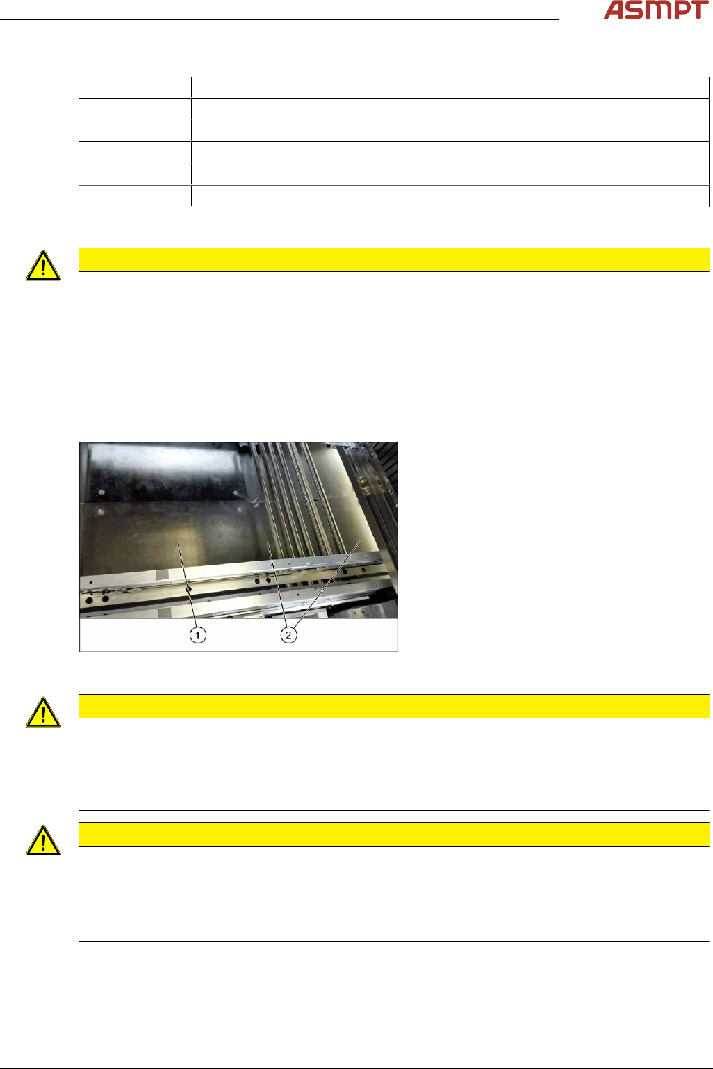
Fig.145: Table plate and covers
► Remove the four screws fastening the lift-
ing table plate(1) (see also Replacing the
Lifting Table Plate [03114873-xx]).
► Cable only: Remove the spacer bolts
fastening the covers(2) (two screws each
cover) and remove the covers.
CAUTION
Make a note of the order in which the cables/fiber optic cables are run!
The room in the conveyor rails is limited. The cables/fiber optic cables may therefore not be crossed
over.
Make a note of the order in which the cables/fiber optic cables are run in the conveyor rail, so that you
can run them neatly and correctly again later on.
CAUTION
Protective tape, do not bend fiber optic cables
There is also a protective tape in the trailing cable. This separates the cables from the fiber optic
cables.
► Make sure you do not bend the fiber optic cables. These will otherwise become cloudy and no
longer transmit the signal properly.