Process Lens PL Service Manual_EN.pdf - 第117页
3 Replacing spare parts Se rv ic e Ma nu al P ro ce ss L en s PL - 0 3/ 20 25 11 7 Fig.159: Clamping plate ► Remove the clamping plate off the con- veyer system by unscrewing the screws (2) using an Allen key size 2.0. …
3 Replacing spare parts
116 Service Manual Process Lens PL - 03/2025
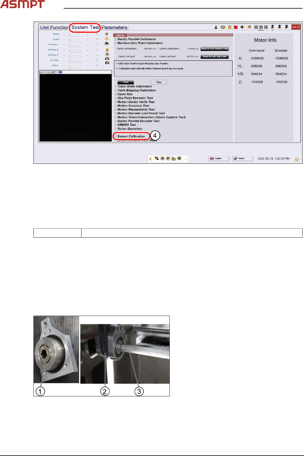
Fig.157: Sensor calibration
► Click on Sensor Calibration(4) to proceed the calibration of the PCB sensor.
3.5.2 Single-lane conveyor
3.5.2.1 Changing the conveyor belt
Parts
03139303-xx Brecoflex timing belt 10T5/2440
Equipment and tools
●
Allen key size 2.0, 2.5, 4
●
Spanner size 10
Requirements
●
Machine is switched off.
●
Tension meter.
Removal
Fig.158: Gear and conveyor rod
► Remove the screw (1) to remove the rod
(3). Use a spanner size 10 and a short
Allen key size 4 to remove the screw (1).
► Move the rod (3) backwards.
3 Replacing spare parts
Service Manual Process Lens PL - 03/2025 117
Fig.159: Clamping plate
► Remove the clamping plate off the con-
veyer system by unscrewing the screws
(2) using an Allen key size 2.0.
WARNING!
Springs inside the clamps (1)
.
The clamps (1) of the conveyer system bear
springs.
Make sure all parts are retained.
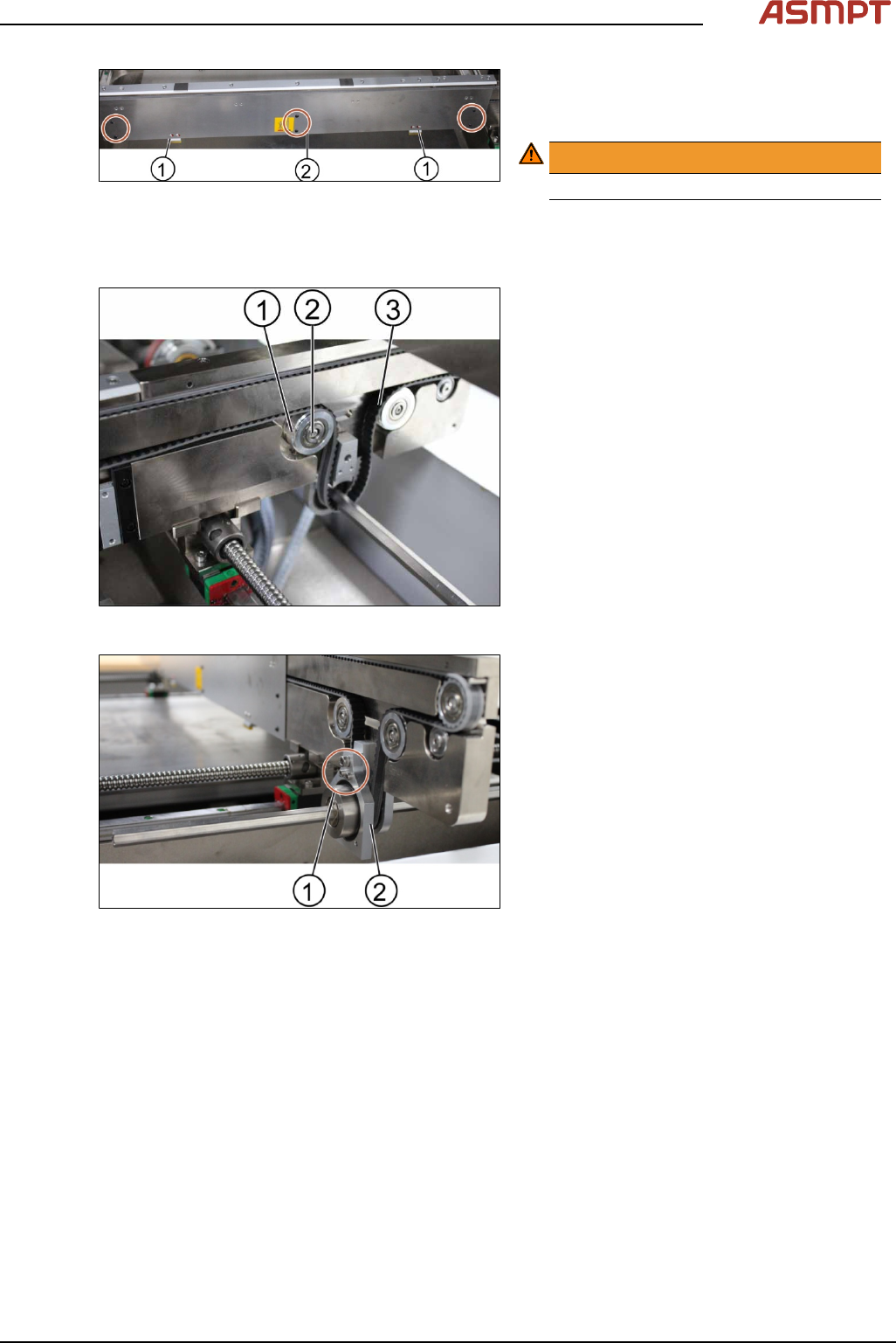
Fig.160: Tension ring of the conveyor unit
► Loose the tension ring (1) of the belt (3) to
release the tension of the belt. Unscrew
the screw (2) by using an Allen key size
2.5.
Fig.161: Gear
► Remove the gear (2).
► Change one screw (1) using an Allen Key
size 4.0 and 2 screws (1) using an Allen
key size 2.5.
► Remove the belt and replace it with a new
one.
► Put back the gear by tighten the screws
(3x).
► Put back the clamping plate by tighten the
screws (6x).
► Put back the tension ring and fasten the
belt by tighten the screw (1x).
3 Replacing spare parts
118 Service Manual Process Lens PL - 03/2025
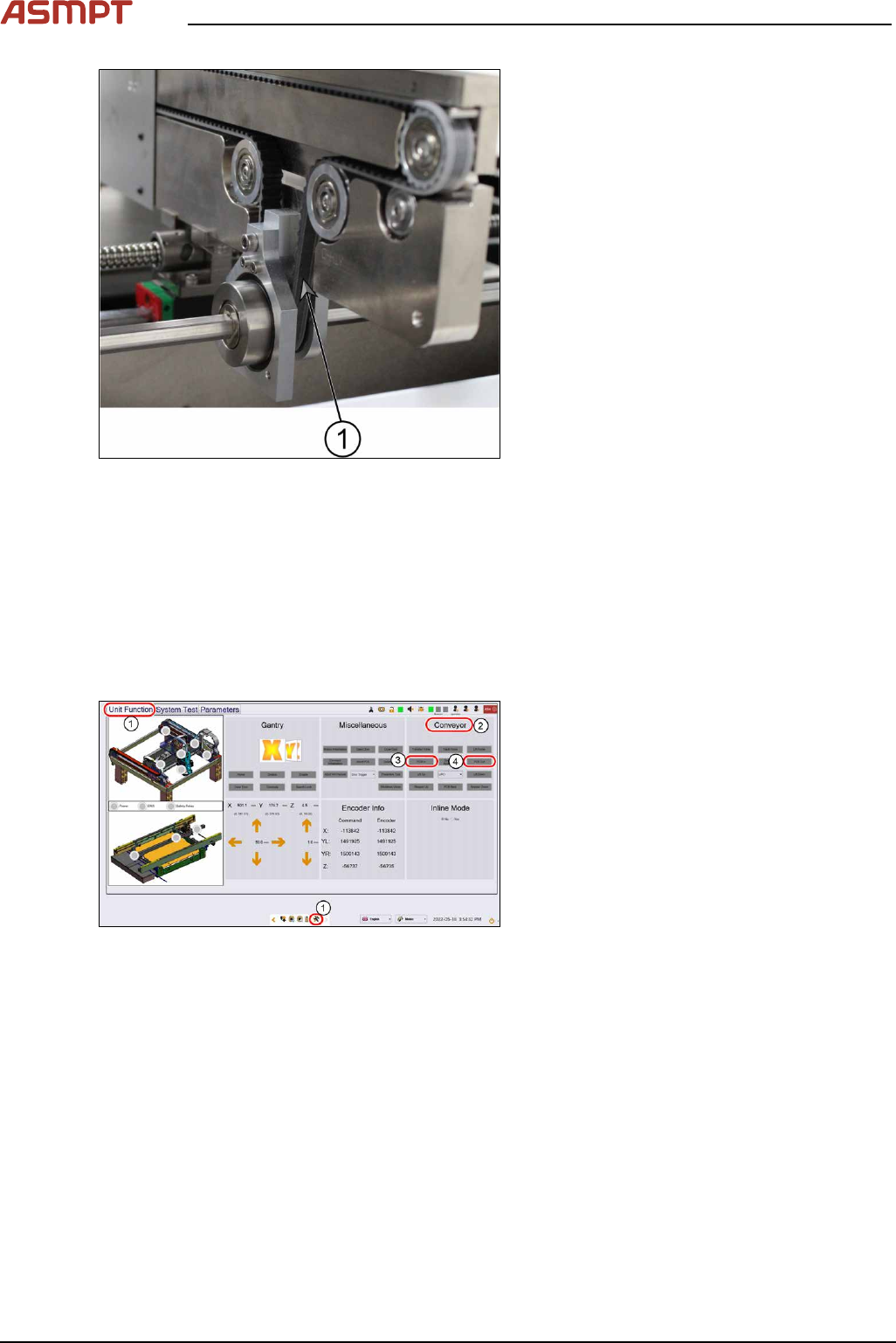
Fig.162: Conveyor belt
► Check the tension of the belt at the meas-
urement point (1) using a tension meter.
The tension should be 250 +/- 10 Hz.
► The steps for the other conveyor system
are the same.
Installation
Follow the removal instructions in reverse order for installation.
Check the function of the conveyor belt
Requirements
●
Machine is switched on.
●
Inspection circuit board is placed at the beginning of the machine.
Fig.163: “Unit Function” tab
► Go to the diagnostic page.
► Click on the tab Unit function(1).
► Go to the section Conveyor(2).
► Click the button PCB In(3) and the button
PCB Out(4).