Process Lens PL Service Manual_EN.pdf - 第144页
4 Machine - Calibrations 14 4 Se rv ic e Ma nu al P ro ce ss L en s PL - 0 3/ 20 25 Step 2 Fig.209: Inspection oage ► Go to Inspection Page (1) . ► Click Adjust Conveyor (2) . ► Set the following: ð Thickness, 4mm (3) ð…
4 Machine - Calibrations
Service Manual Process Lens PL - 03/2025 143
Step 4
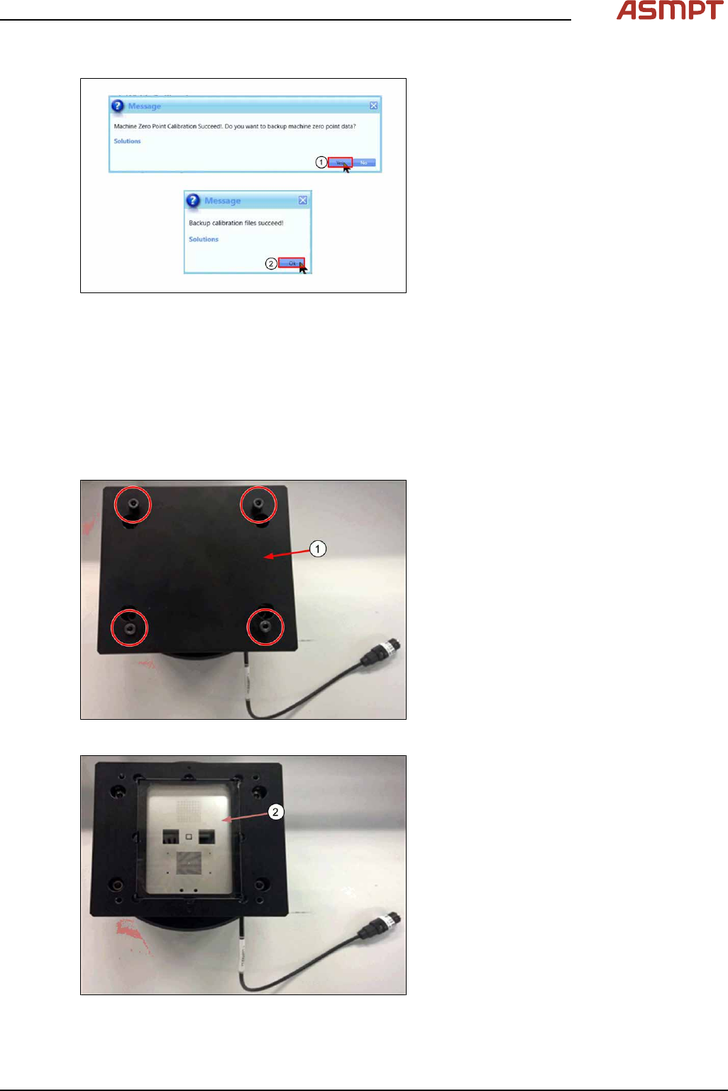
Fig.206: Messages
► Click Yes (1) to backup data.
► Click Ok (2) to complete calibration.
4.3 Calibrations - One Point Dynamic Test
The One Point Dynamic Test test the accuracy of the stopping position after a gantry move. A com-
mand is given to move the camera away from the target, then return to the target and the variation
between the theoretical and actual stop position as measured by the camera is analysed. The process
is repeated 50 times.
Step 1
Fig.207: Removing the cover
► Remove the cover (1) by removing the
4screws.
Fig.208: Checking glass target
► Check the glass target (2) for scratches or
damage. Clean with lint free cloth & IPA if
necessary.
4 Machine - Calibrations
144 Service Manual Process Lens PL - 03/2025
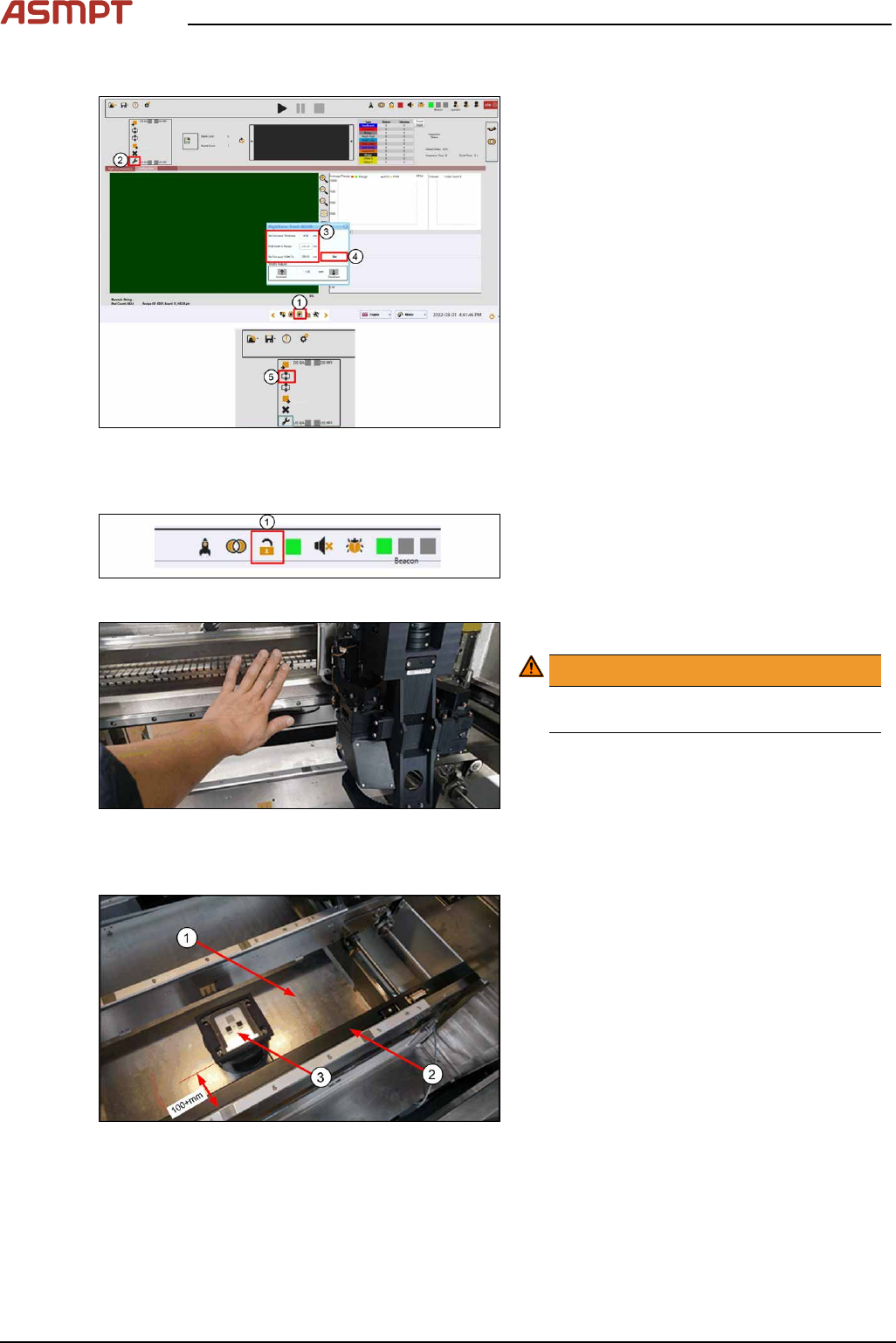
Step 2
Fig.209: Inspection oage
► Go to Inspection Page (1).
► Click Adjust Conveyor (2).
► Set the following:
ð Thickness, 4mm (3)
ð Width, 250mm (3)
► Click Set (4).
► Click Lift Up (5) to lift up lifting table.
Step 3
Fig.210: Opening door
► Click Lock to open door (1).
Fig.211: Pushing the gantry
► Push the gantry to the back.
WARNING!
Do not push on the camera module.
Remove all supporting pins.
.
Step 4
Fig.212: Placing the target
► (1) Clean the lift table of any debris.
► (2) Pull the sensor bar towards the front
conveyor.
► (3) Place the target on the table in the
middle of the conveyor about 100+mm
away from the front conveyor´s edge.
Align the target parallel to the conveyor.
4 Machine - Calibrations
Service Manual Process Lens PL - 03/2025 145
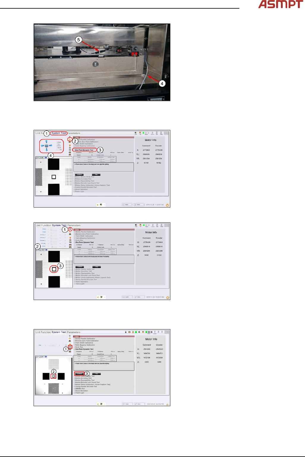
Fig.213: Connecting the cables
► (4) Loop the lighting cable from the right of
the lift table through the gap and over the
conveyor ball screw as shown. This will
prevent the cable from getting crushed
when the lift table is raised.
► (5) Connect the lighting cable from the
machine to the target.
Step 5
Fig.214: “System test” tab
► Click System Test (1).
► At Utility, select One Point Dynamic Test
(3).
► Click on Jogging (2).
► Click on the directional arrows (4) to jog
the camera over to the target until the
square target comes into view.
Fig.215: Setting the lighting
► At the Lighting Box menu (1), set 2D
Back lighting (2) to 25 and all other light-
ing values to0.
► Click the centre (3) of the square target.
The camera centres the FOV to the
square target.
Step 6
Fig.216: Focus
► Click on Focus icon (1).
► Set value between 50~60 till image is
clear.
► Click Continue (3) to proceed calibration.