Process Lens PL Service Manual_EN.pdf - 第152页
4 Machine - Calibrations 15 2 Se rv ic e Ma nu al P ro ce ss L en s PL - 0 3/ 20 25 ► Reconnect the Low Ring light connector. ► Open the machine cover. NOTICE The mapping information is stored in C:\system\Log\TableMappi…
4 Machine - Calibrations
Service Manual Process Lens PL - 03/2025 151
Step 6
Fig.229: “Focus” Icon
► Click on Focus icon (1).
► Set value (2) between 50 ~ 60.
► Click Continue (3) to start the teach table
mapping process.
The progress of the mapping is continu-
ously reported.
NOTICE
At 50% completion, the table towers, the stopper rises, and the plate will move forward to the stopper
to continue the second stage of the mapping. Do not be alarmed by this sudden movement. No user
intervention is required.
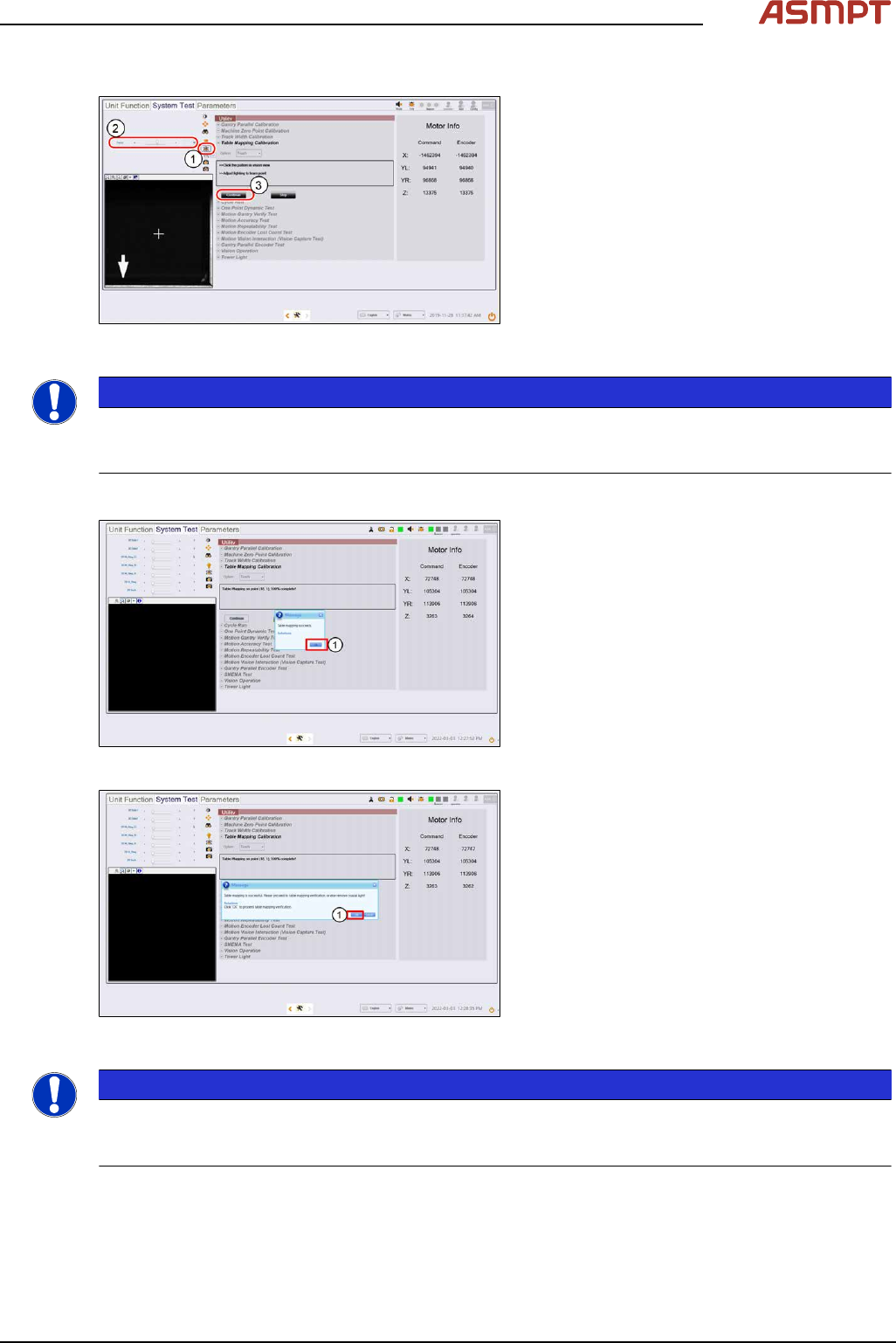
Step 7
Fig.230: Message
► A message pops up to report if the teach
process is completed.
Click Ok (1).
Fig.231: Message
► At the next message (2),
click OK to continue with verification (see
section Table Mapping: Verify)
or Cancel to end mapping teach.
NOTICE
If the mapping fails, clean the plate and repeat the procedure. Mapping failures are caused by a fail-
ure to read a fiducial on the plate – usually caused by fingerprint smudges on the fiducials. Verifica-
tion of the mapping results is necessary after a successful Teach.
► Lower the conveyor lift cable.
► Open the machine cover.
► Remove the mapping plate.
► Uninstall the coaxial light.
4 Machine - Calibrations
152 Service Manual Process Lens PL - 03/2025
► Reconnect the Low Ring light connector.
► Open the machine cover.
NOTICE
The mapping information is stored in C:\system\Log\TableMapping_timestamp*.log file (approx.
459KB).
The Delta of Gantry to fiducials` positions should be ≤ 20µm (0.020mm).
4.4.2 Table Mapping: Verify
For verification of positional accuracy of the camera across the work area.
Verify saves time. It takes only 5.5 minutes compared to 63 minutes in Teach.
The procedure is similar to the Teach procedure.
Verify the table mapping again if:
●
The machine is already calibrated but is moved.
●
The positional accuracy of the camera across the work area is suspect.
●
Maintenance is performed on the gantry axes e.g. greasing.
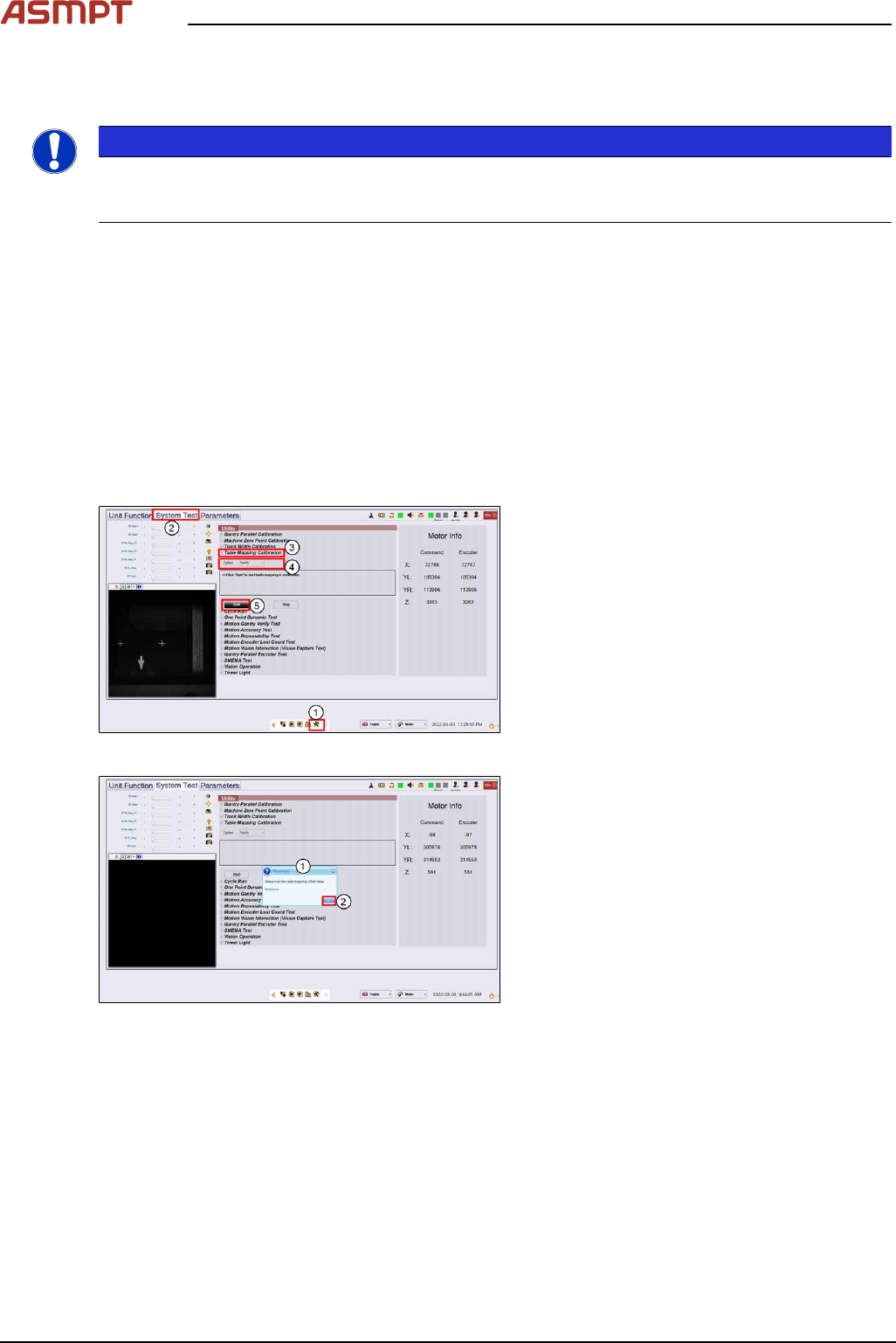
Step 1
Fig.232: “System Test” tab
► Go to the DiagnosticPage (1).
► Click System Test (2).
► Go to Utility, Table Mapping Calibration
(3).
► Under Option, select Verify (4).
► Click Start (5).
Fig.233: Message
► A message asking for the mapping data
file pops up. (1)
► Click Ok (2).
4 Machine - Calibrations
Service Manual Process Lens PL - 03/2025 153
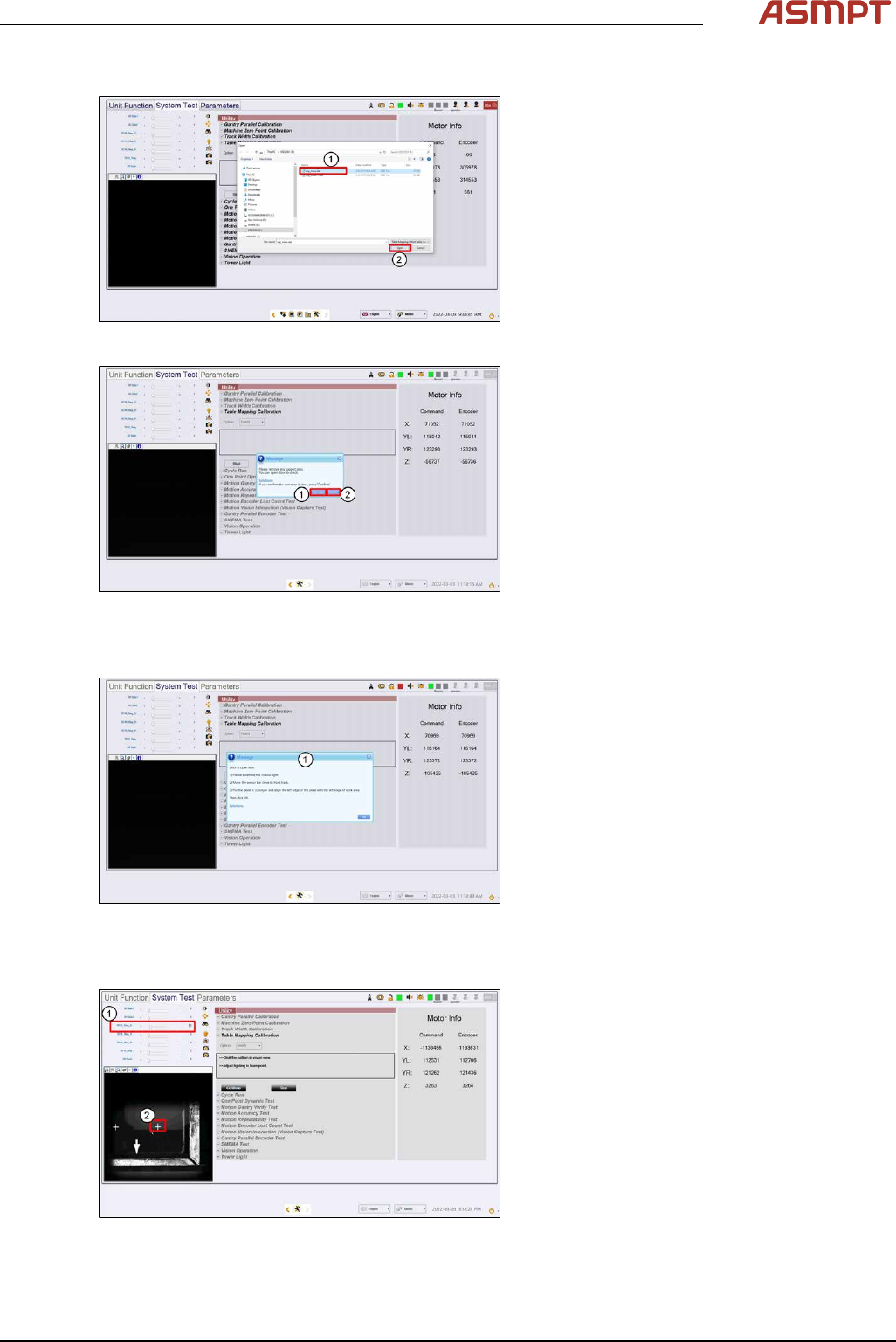
Step 2
Fig.234: Choosing the file
► Choose the mp_mess.dat file (1).
► Click Open (2), data loading.
Fig.235: Confirming message
► A message asking to remove any support
pins pops up. Click Open door(1).
► Click Confirm (2).
► Wait while the conveyor adjust to a width
of 560mm. (3)
Step 3
Fig.236: Installing the Assembly
► A message pops up after the conveyor
width reaches 560mm (1). Open the
machine cover.
► Install the Coaxial Light Assembly and
position the Mapping Plate on the con-
veyor.
► Click Ok.
Step 4
Fig.237: Setting values
► Set 2D M-Ring_G (1) about 10 and all
other lighting values to 0.
► The plate´s bottom right hand cross fidu-
cial comes into view. Click on the cross (2)
to centre the cross to the FOV.