Process Lens PL Service Manual_EN.pdf - 第31页
3 Replacing spare parts Se rv ic e Ma nu al P ro ce ss L en s PL - 0 3/ 20 25 31 Installation ► Follow the removal instructions in reverse order for installation. Also observe the following instruction: Fig.23: Aligning…
3 Replacing spare parts
30 Service Manual Process Lens PL - 03/2025
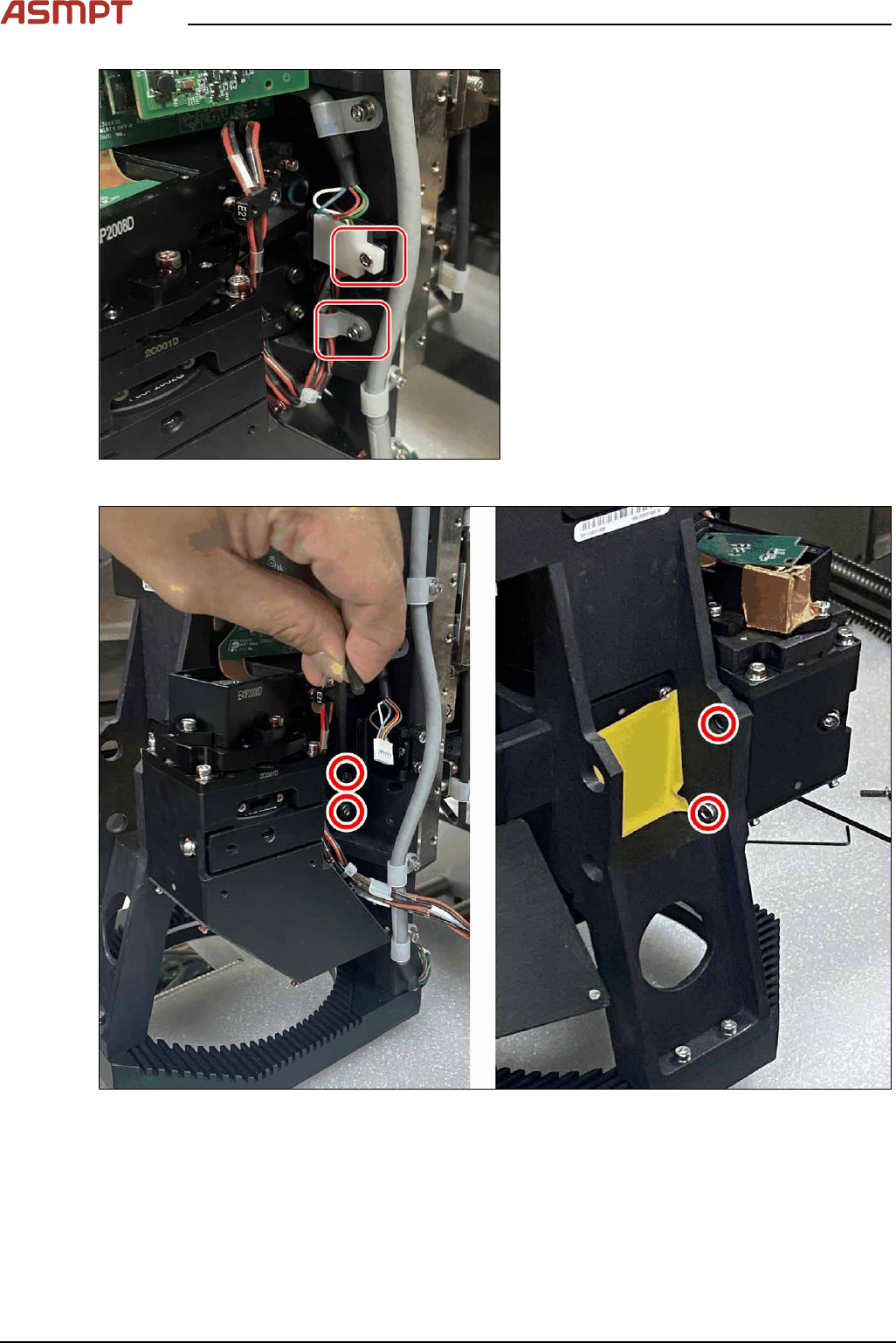
Fig.21: Removing the screws
► Remove the two screws that hold the
cable and the cable holder.
Fig.22: Removing the screws
► Remove the four screws that secure the module.
► Remove the module.
3 Replacing spare parts
Service Manual Process Lens PL - 03/2025 31
Installation
► Follow the removal instructions in reverse order for installation. Also observe the following
instruction:
Fig.23: Aligning the module
► Align the module with the help of the two guide pins.
Checking for connectivity
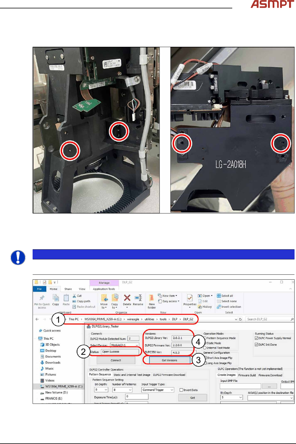
NOTICE
Make sure the machine is installed with the latest software version. Otherwise, the DLP Test software
will return an error message.
Fig.24: Checking connectivity
3 Replacing spare parts
32 Service Manual Process Lens PL - 03/2025
► Open the file c:\wineagle\utilities\tools\DLP\DLP_G2\DLPG2Library_Tester(1) on the station
computer.
► Select Left DLP ModuleID:0(2) and right DLP ModuleID:1(2) one at a time.
► Click on Get Version (3).
ð The data shown mean that DLP is connected to DMD(4).
► Start the Process Lens station software from your Windows Desktop.
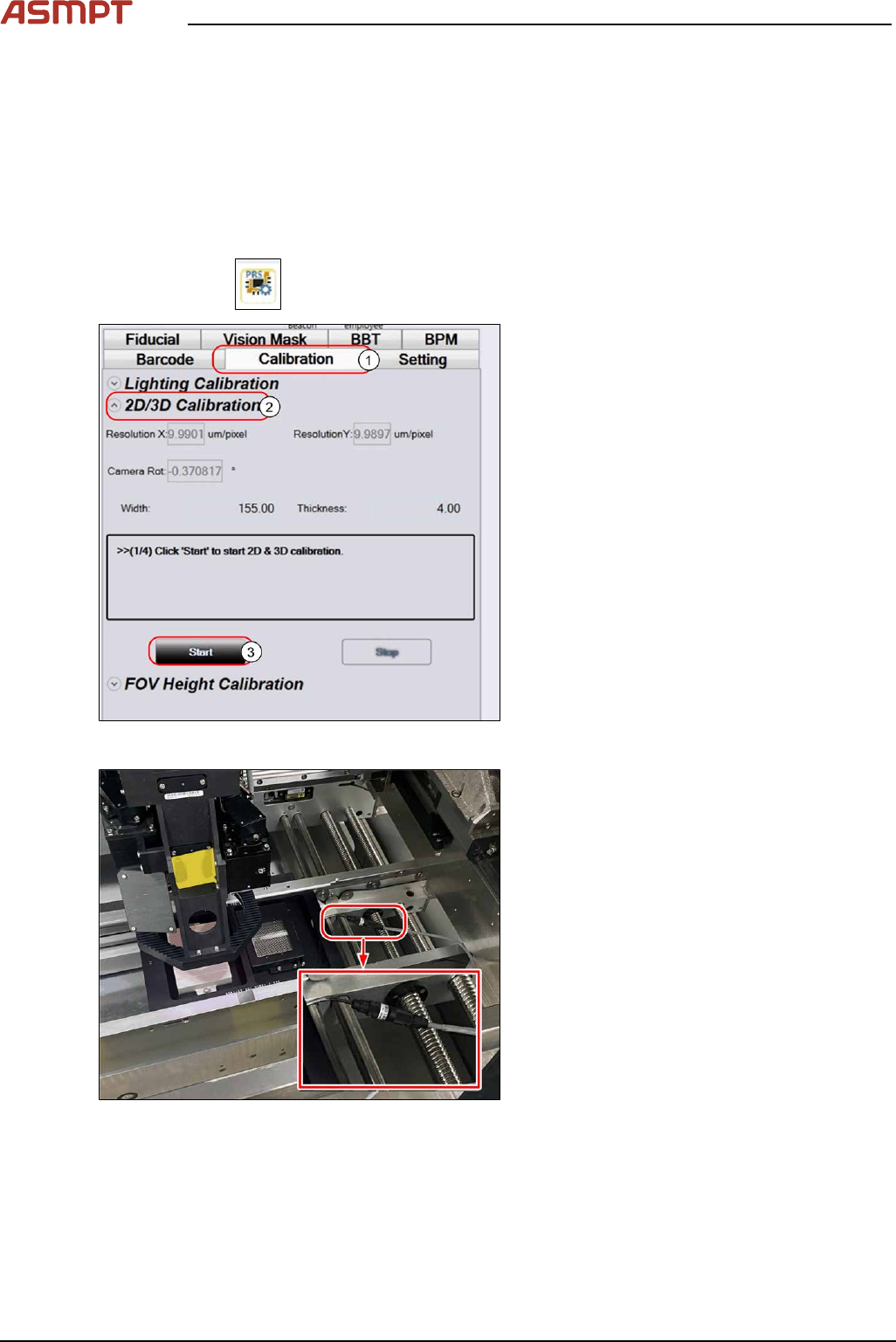
Checking B/A Value
► Click on the
button at the bottom of menu on the GUI.
Fig.25: 2D/3D Calibration
► Select the Calibration tab(1).
► Under 2D/3D Calibration(2) click on
Start(3).
ð The jig is transported from the input
section of the conveyor to the inspec-
tion area.
► Follow the GUI instructions.
Fig.26: Connecting the backlight cable
► Connect the backlight cable.
► At the end of the GUI instructions click OK to proceed.