Process Lens PL Service Manual_EN.pdf - 第51页
3 Replacing spare parts Se rv ic e Ma nu al P ro ce ss L en s PL - 0 3/ 20 25 51 Fig.60: Calibration of the new reader ► Check the gap between the encoder reader (1) and the scale bar (2) by using the spacer (3) prov…
3 Replacing spare parts
50 Service Manual Process Lens PL - 03/2025
3.3 Encoder
3.3.1 Replacing the encoder reader at the x, y and z gantry
Parts for Process Lens PL
03122960-xx Tonic encoder interface 0.1UM
(Encoder reader X, Y, Z)
Parts for Process Lens PL Single-Lane
03157187-xx X Encoder Assy
03157188-xx Y Gantry Left Encoder Assy
03157190-xx Y Gantry Right Encoder Assy
03153580-xx Z axis encoder
Equipment and tools
●
Allen key size 2.0
●
Spacer 2.1mm
Requirements
●
Machine is switched off.
Removal and Installation
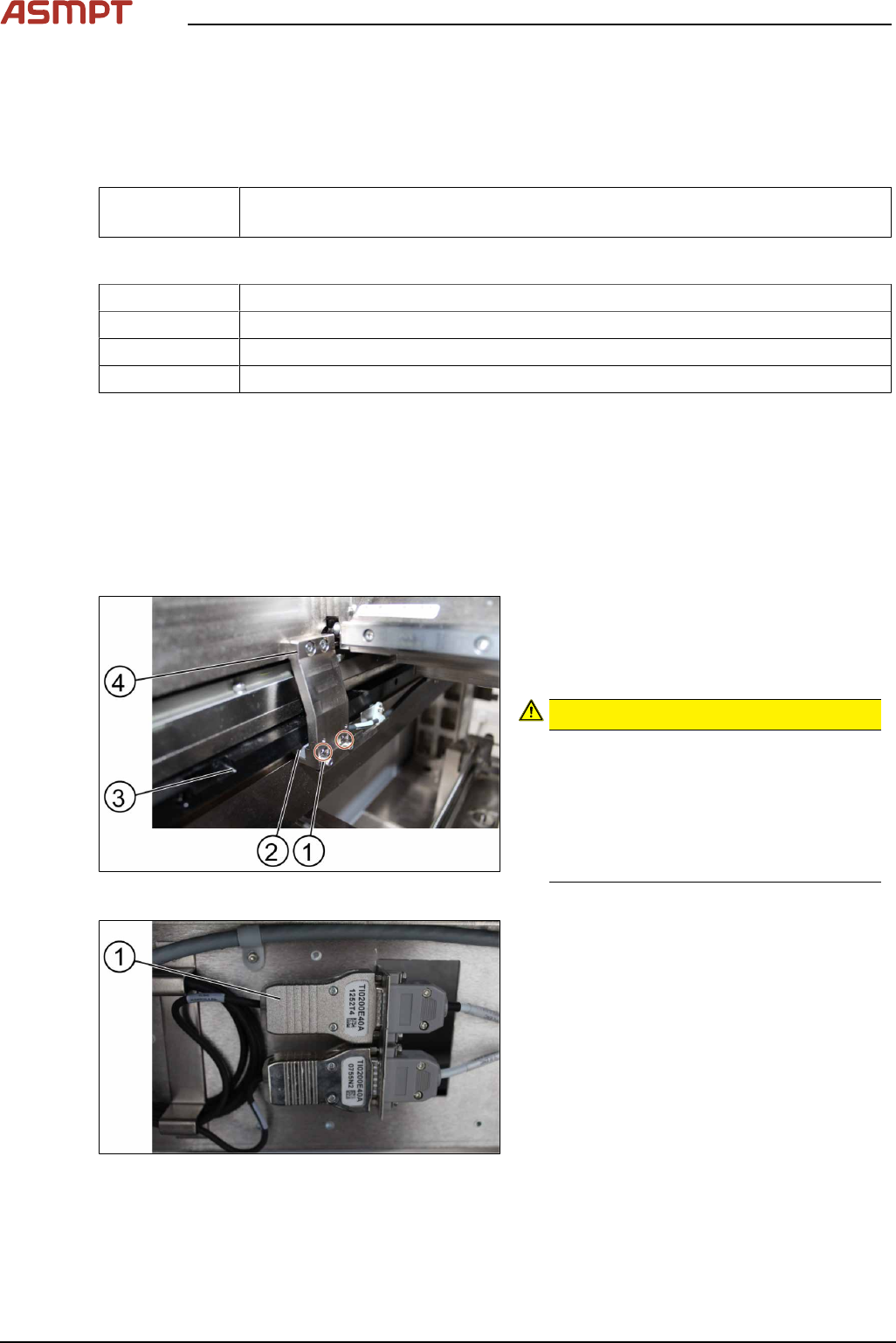
Fig.58: Removing the screws
► Remove the two screws(1) using an Allen
T shaped Allen key size 2.0.
► Carefully pull out the encoder reader(2).
The scale of the scale bars
CAUTION!
Fingerprints or scratches damage the
scale bars(3) which then need to be
exchanged.
Do not touch or scratch the scale of the
scale bars.
Be careful when pulling out the reader
and when putting it back again.
.
Fig.59: Changing the reader
► Change the reader including the en-
coder(1) and all cables.
► Replace the encoder and the reader.
3 Replacing spare parts
Service Manual Process Lens PL - 03/2025 51
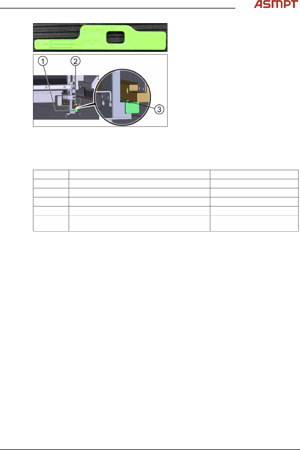
Fig.60: Calibration of the new reader
► Check the gap between the encoder
reader(1) and the scale bar(2) by using
the spacer(3) provided.
► The gap between the encoder reader and
the scale bar must be 2.1 mm.
► Calibrate the new reader. See the external
Power Point file “Y1Y2 ENC install & ad-
just procedure”.
► Move the gantry slowly the whole travel
range backwards. Whilst doing that check
the light at the indicator.
► If the lights are not within the color range
the holder needs adjustments. See 3.3.2
"Color code for the encoder readers"
[}51].
► Proceed the same way with all other en-
coder readers.
3.3.2 Color code for the encoder readers
Color Indication Adjustment requirement
Purple Optimum set-up No
Blue Good set-up No
Green Good set-up No
Orange Acceptable set-up but below recommendation level. Yes, angle and gap.
Red Poor set-up, signal maybe too low for reliable oper-
ation
Yes, angle and gap.
3 Replacing spare parts
52 Service Manual Process Lens PL - 03/2025
3.3.3 Checking the alignment of the encoder reader of the Y gantry
Whenever the encoder readers and/or scale bars have been removed, they need to be realigned.
Requirements
●
Machine is switched on.
●
Optical head is centered on the X position.
Checking the alignment
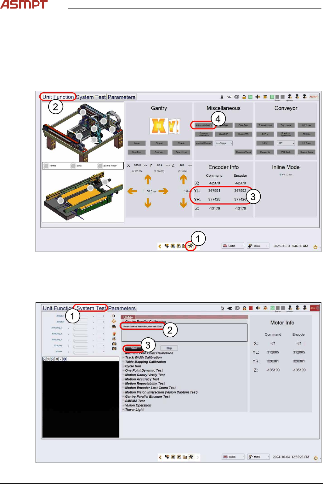
Fig.61: “Unit Function” tab
► Select the Unit Function tab(2) on the Diagnostic Page(1).
► Check the value differences between YL & YR under Encoder Info(3). Adjust them if necessary
(see 3.3 "Encoder" [}50])
► Click Motion Initialisation(4) to reset all NuMotion values.
Fig.62: “System Test” tab