Process Lens PL Service Manual_EN.pdf - 第54页
3 Replacing spare parts 54 Se rv ic e Ma nu al P ro ce ss L en s PL - 0 3/ 20 25 3.4 Scale bars 3.4.1 Replacing the Y scale bars Parts Fig.66: Y scale bar, 2 Scale 03139293-xx Y scale assembly 03139296-xx X scale assemb…
3 Replacing spare parts
Service Manual Process Lens PL - 03/2025 53
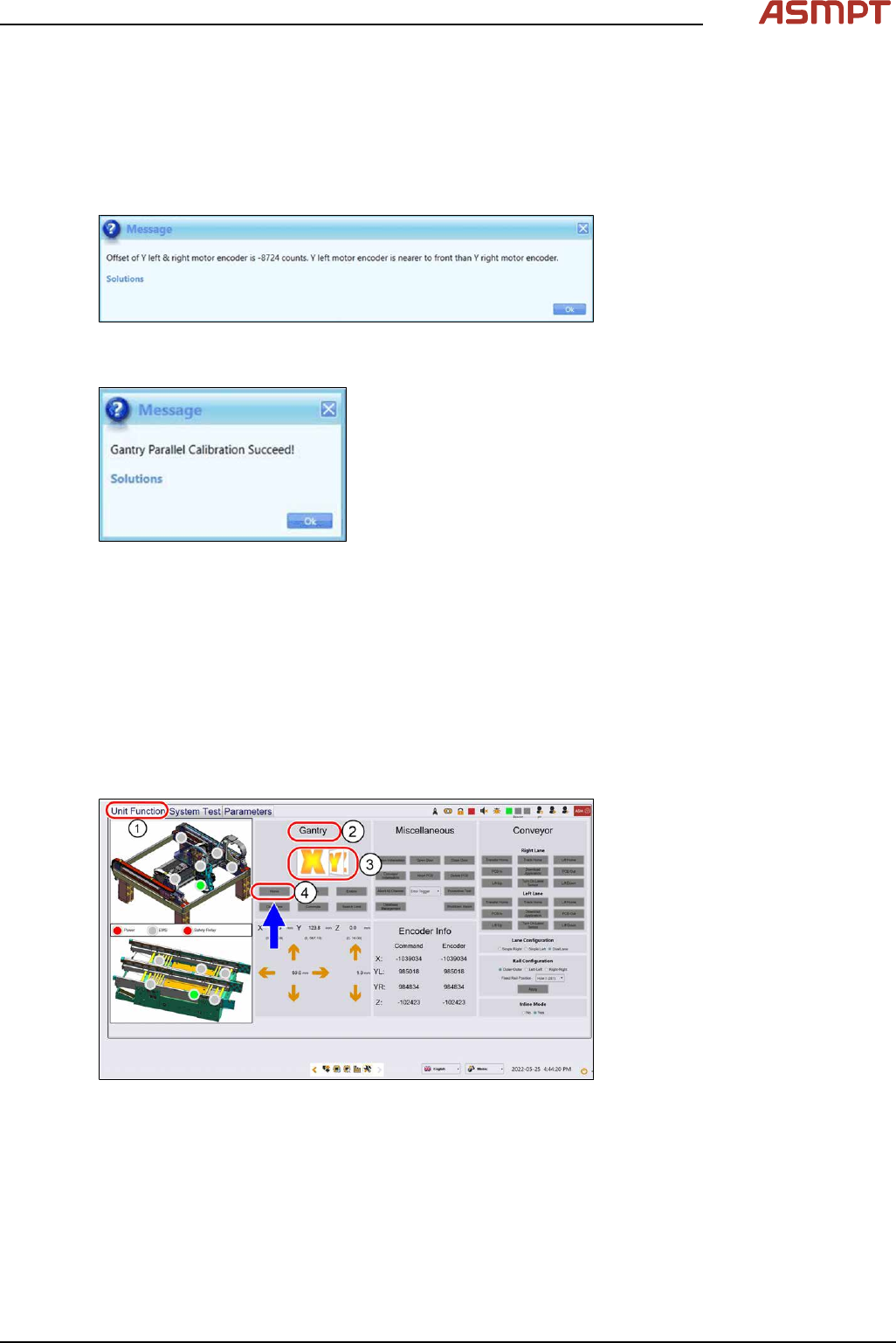
► Select the System Test tab(1).
► Ignore the message “Please lock the flexure first” in the message window (2) under Gantry Par-
allel Calibration. This step is not necessary.
► Click Start(3) to continue, the calibration status will update on the message window.
► A pop-up message will show the encoder count. Adjust the encoder if the value does not fall
within 10,000-digit. See also 3.3 "Encoder" [}50].
Fig.63: Message showing encoder counts
► Click Ok, a success message will appear at the end.
Fig.64: Success message
► Click Ok and the calibration is completed.
3.3.4 Checking the alignment of the x, y and z encoder reader
Furthermore the alignment of the x, y and z readers need to be checked whenever the readers or the
scale bar has been changed.
Requirements
●
Machine is switched on.
Checking the alignment
Fig.65: Checking the alignment
► Go to the Diagnostic page.
► Click on the Unit function(1) tab.
► Go to the Gantry section(2).
► Select the X button(3) and click on Home(4).
► Select the Y button(3) and click on Home(4).
► Select the Z button(3) and click on Home(4).
3 Replacing spare parts
54 Service Manual Process Lens PL - 03/2025
3.4 Scale bars
3.4.1 Replacing the Y scale bars
Parts
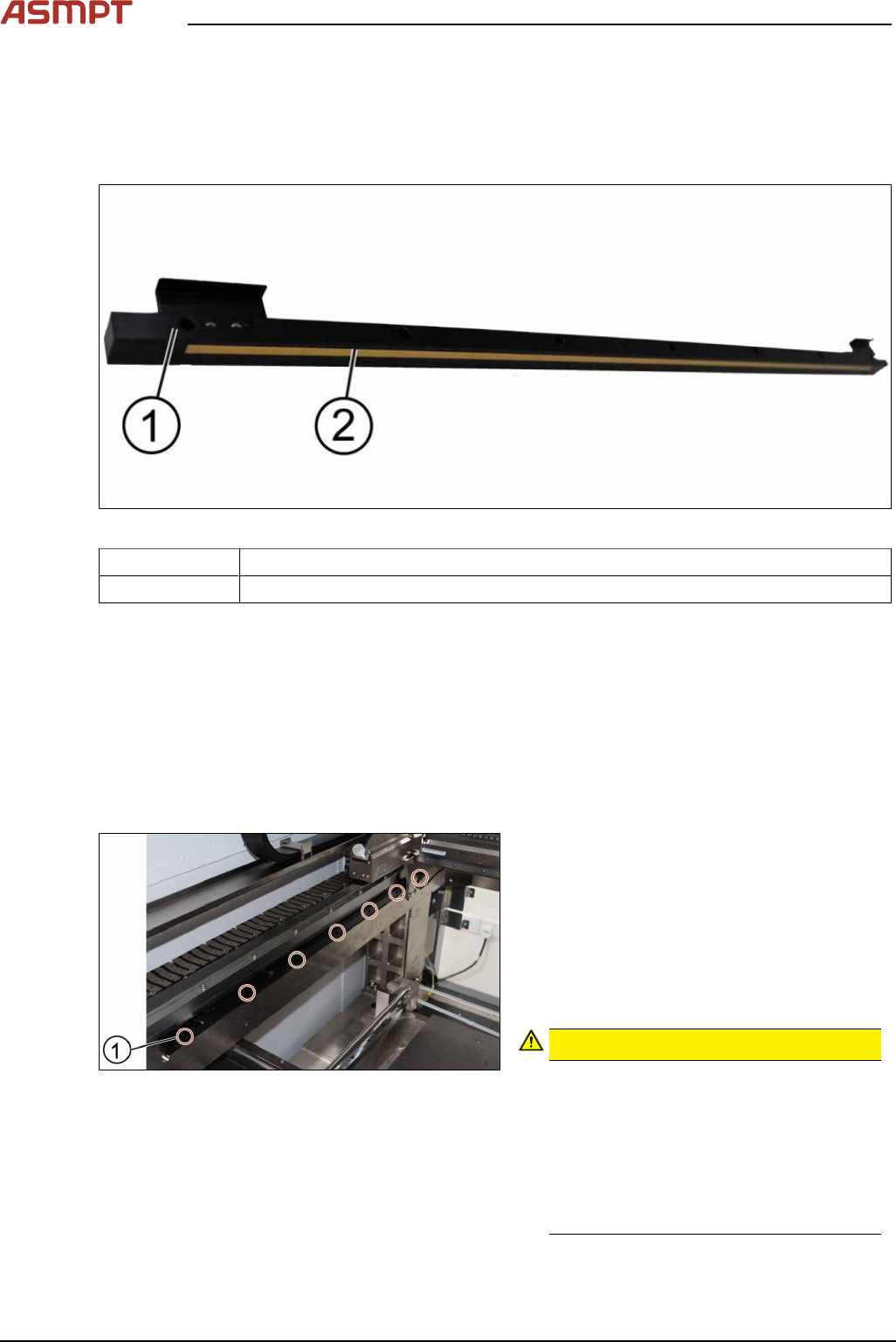
Fig.66: Y scale bar, 2 Scale
03139293-xx Y scale assembly
03139296-xx X scale assembly
Equipment and tools
●
Allen key size 2.5
●
Spacer 2.1mm
●
Piece of paper
Requirements
●
Machine is switched off.
Removal and installation
Fig.67: Removing the screws
► Unscrew and remove the seven screws(1)
off the scale bar using a T shaped Allen
key size 2.5.
► Carefully pull out the scale bar.
► Do not damage the encoder reader. The
sensitive reader may be protected by
using a piece of paper.
► Put in the new scale bar.
CAUTION!
The surface of the scale bars
Fingerprints or scratches damage the
scale bars which then need to be ex-
changed.
Do not touch or scratch the surface of the
scale bars.
Be careful when pulling out the reader
and when putting it back again.
.
3 Replacing spare parts
Service Manual Process Lens PL - 03/2025 55
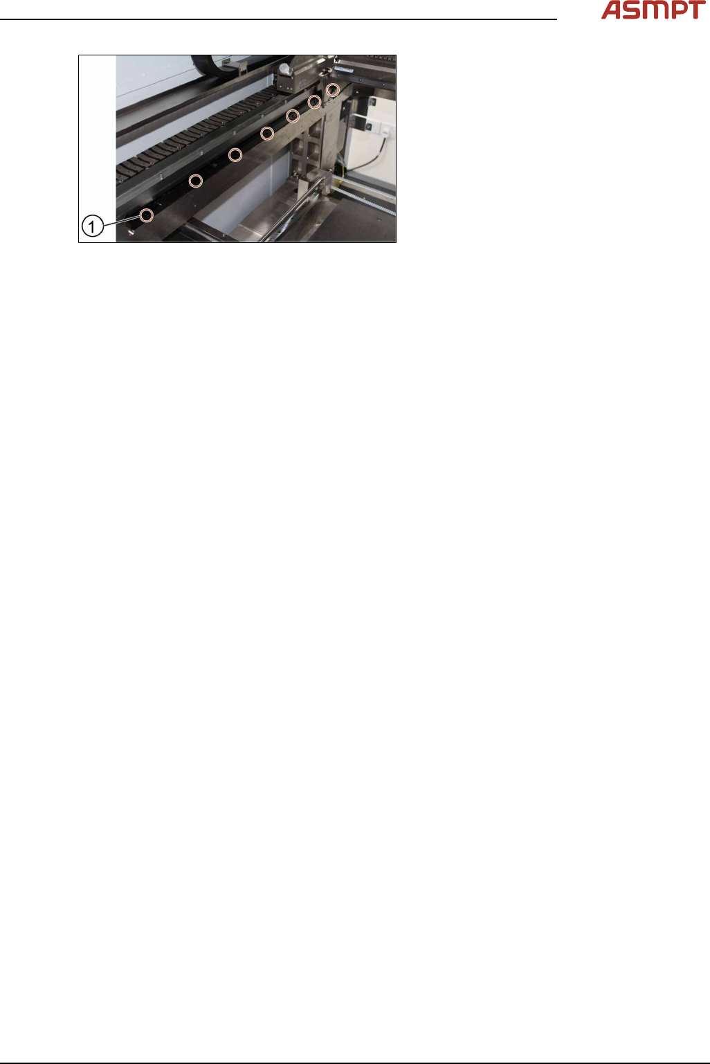
Fig.68: Tightening the screws
► Tighten the seven screws(1).
► Check the space between the reader and
the scale bar by using the 2.1 mm spacer
provided.
► Check the lights of the encoder at the back
of the machine.
► Slowly move the gantry backwards and
forwards. See section 3.3.2 "Color code for
the encoder readers" [}51].
► Adjust the brackets when the lights indic-
ate to do so.
► The steps to change the other scale bar are identical.
► Check the alignment of the y scale bar. Go to section 3.3.3 "Checking the alignment of the en-
coder reader of the Y gantry" [}52] and section 3.3.3 "Checking the alignment of the encoder
reader of the Y gantry" [}52].
► Tighten the seven screws(1).
► Check the space between the reader and the scale bar by using the 2.1 mm spacer provided.
► Check the lights of the encoder at the back of the machine.
► Slowly move the gantry backwards and forwards. See section 3.3.2 "Color code for the encoder
readers" [}51].
► Adjust the brackets when the lights indicate to do so.
► The steps to change the other scale bar are identical.
► Check the alignment of the y scale bar. Go to section 3.3.3 "Checking the alignment of the en-
coder reader of the Y gantry" [}52] and section 3.3.3 "Checking the alignment of the encoder
reader of the Y gantry" [}52].