Process Lens PL Service Manual_EN.pdf - 第8页
1 Introduction 8 Ser vi ce M an ua l Pr oc es s Le ns P L - 03 /2 02 5 1.1.5 Notes on switching the machine back on CAUTION Residual voltages ► After switching off the machine, wait at least 10 seconds before you switch …
1 Introduction
Service Manual Process Lens PL - 03/2025 7
1.1.4 Residual voltages and discharge times in the machine
1.1.4.1 Energy state of the machine after the EMERGENCY STOP button is pressed
If the EMERGENCY STOP button is pressed, the voltage are reduced to harmless residual voltages in
a very short time.
WARNING
Some parts of the system carry potentially lethal voltages
The machine is supplied with 1/N/PE ~ 240, 50/60 Hz mains voltage. This means that some parts of
the system carry potentially lethal voltages - even when switched off at the main power switch. Incor-
rect handling of the machine can therefore result in death or severe injury or considerable damage to
equipment.
► Always follow the applicable accident prevention and safety regulations (particularly DIN EN
60204, part 1 or IEC 60204, part 1) and the safety regulations in your own country.
► The covers over the power supply unit may ONLY be opened by appropriately qualified and
trained personnel.
NOTICE
Process Lens PL electrical diagrams
For details, please refer to the Process Lens PL electrical diagrams.
1.1.4.2 Energy state of the machine after switching off the main power switch
WARNING
Some parts of the system carry potentially lethal voltages
The machine is supplied with 1/N/PE ~ 240, 50/60 Hz mains voltage. This means that some parts of
the system carry potentially lethal voltages - even when switched off at the main power switch. Incor-
rect handling of the machine can therefore result in death or severe injury or considerable damage to
equipment.
► Always follow the applicable accident prevention and safety regulations (particularly DIN EN
60204, part 1 or IEC 60204, part 1) and the safety regulations in your own country.
The following components still carry potentially lethal voltages even if the main power switch is
switched off:
●
Mains connection terminals of the main power switch.
NOTICE
Process Lens PL electrical diagrams
For details, please refer to the Process Lens PL electrical diagrams.
To avoid losing data, assess the following criteria before switching off your machine (apart from in
emergencies):
●
Has the machine finished transmitting machine and recipe data?
●
Has the machine finished processing the PCB?
●
Has the machine software completed the shot-down phase?
Machine switched off at the main power switch and disconnected
The machine is unpowered, apart from slight residual voltages in the power supply unit.
1 Introduction
8 Service Manual Process Lens PL - 03/2025
1.1.5 Notes on switching the machine back on
CAUTION
Residual voltages
► After switching off the machine, wait at least 10 seconds before you switch it back on again, so
that stored residual voltages can dissipate.
► Please note that longer waiting periods apply when working on the power supply.
1.1.6 Safety instructions for the gantry
CAUTION
Moving the gantry can damage the Vision Module.
When moving the gantry, observe the following:
► NEVER move the gantry by pushing with your hands against the placement head.
1.1.7 Safety instructions on hazardous materials
CAUTION
Observe the safety data sheets
Observe the applicable safety data sheet, when handling hazardous materials (e. g. Loctite 241, eth-
anol).
1.1.8 Classification of the optical systems
1.1.8.1 Classification of the whole machine
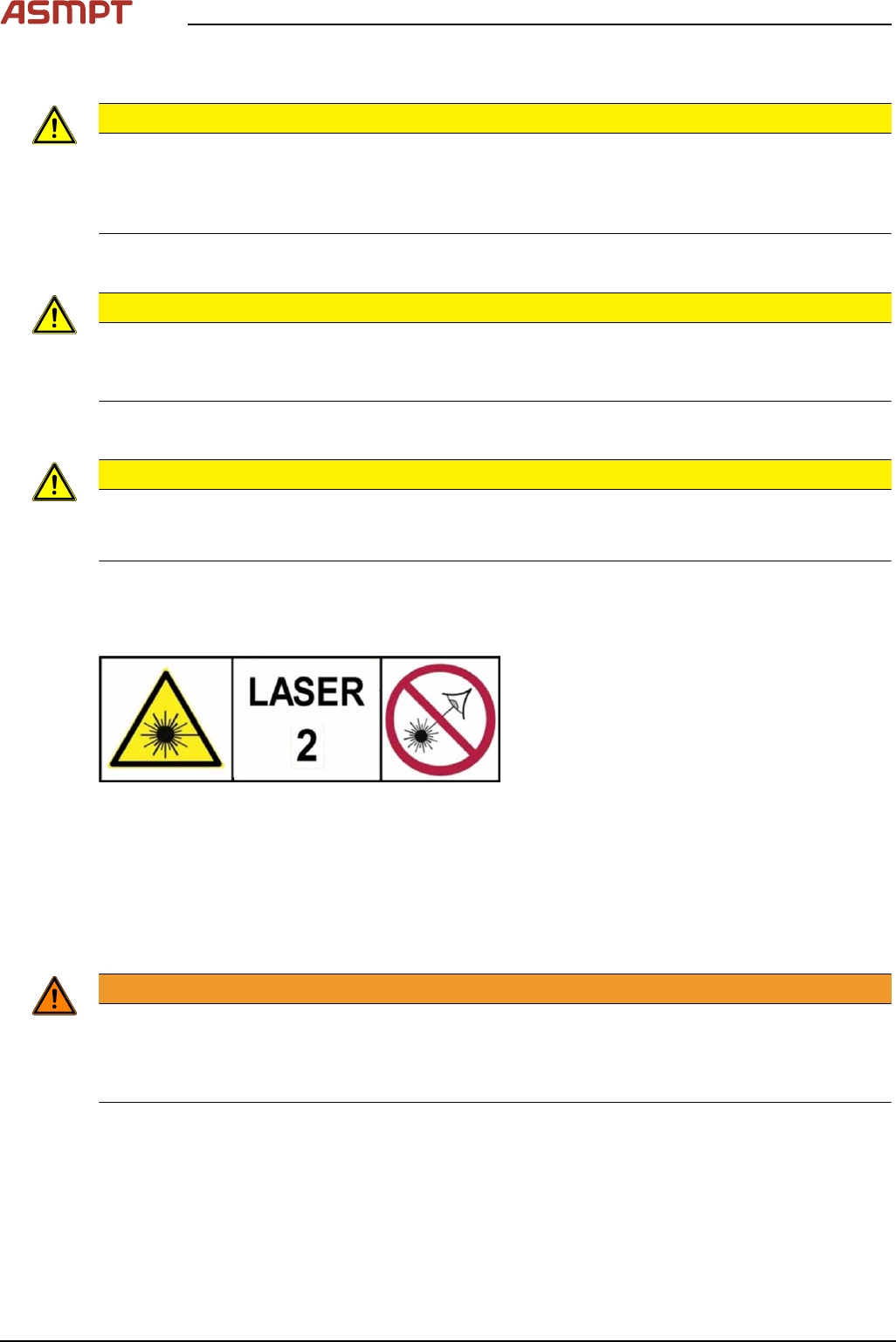
Fig.1: Laser class 2
The ready-to-operate overall machine is as-
signed to laser class°2.
The laser classes are determined according to
DIN EN 60825-1:2014.
1.1.8.2 Laser classification
The following modules are assigned to laser class 2:
●
Laser light barriers at the board conveyor
1.1.8.3 Classification of the camera systems
WARNING
LEDs
The camera illumination systems are fitted with light LEDs. These are assigned to risk group 1 accor-
ding to IEC 62741:2006.
► Do not look into beam!

1 Introduction
Service Manual Process Lens PL - 03/2025 9
1.2 Lock out and tag out procedure
1.2.1 Purpose and scope
Before performing any preventive maintenance work, conversion work or service work, a procedure of
locking and tagging must be followed and warning signs must be attached if not stated otherwise. If it
is not necessary to switch off the machine, it is explicitly mentioned.
The procedure, when followed, correctly eliminates the possibility of an employee being injured.
NOTICE
Additional safety measures
These procedures represent the minimum lock/tag out requirements for the machine during prevent-
ive maintenance work and service work. Any additional safeguards needed to complete work safely
can be specified by facilities supervision, the safety officer, the safety committee and the health de-
partment.