5OM-1610-002_w.pdf - 第75页
5OM-1610 1-22 101 1-001
5OM-1610
1-21
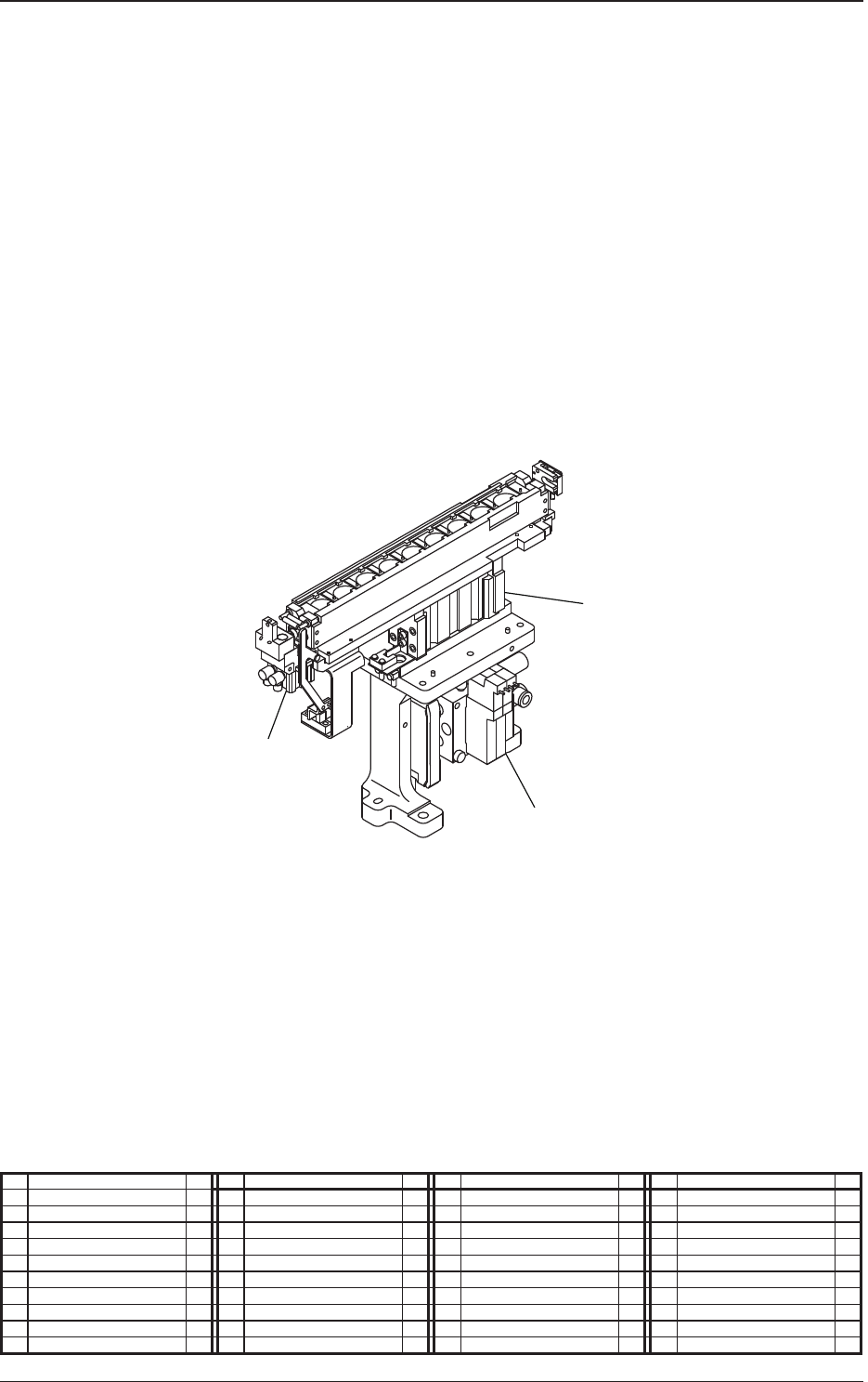
Pneumatic and Mounting Diagrams
No. Name Q’ty No. Name Q’ty No. Name Q’ty No. Name Q’ty
2 Solenoid Valve 1
4 Cylinder 1
5 Cylinder 1
Multi Function Nozzle Stocker (Mounting Diagram)
4
2
5
1011-002-(08303)

5OM-1610
1-221011-001

5OM-1610
0911-001 2-A
Chapter 2
Sensor and Load Layout
This chapter indicates where the sensors and loads are located in each
section.
As this contains highly sophisticated contents, it should carefully be
referred to.