C371347_139780418F8DFE40697A24CD62AD2CE5.pdf - 第14页
CM108B USB Audio Single C hip Datasheet Revision: 1.11 www .cmedia.com.tw P age 14 / 24 Copyright© C -Media Electr onics Inc. bit[1] R eserved, should be 0 bit[0] R eserved, should be 0 ~ END 7.1.4 EEPROM SPI interface t…
CM108B
USB Audio Single Chip
Datasheet Revision: 1.11 www.cmedia.com.tw
Page 13 / 24 Copyright© C-Media Electronics Inc.
7.1.3 Content format for EEPROM (93C46)
Each address has 2-byte data, prefix `0x` means hex number
Address(Hex)
Description
0x00
bit[15:4] Magic Word
0x670X where X = bit 4, 3, 2, 1
bit[3] The value within address 0x2A, 0x2B, 0x32 is valid 1: valid 0: invalid
bit[2] reserved, should be 1
bit[1] serial number enable control 1: enable, 0: disable(default)
bit[0] reserved, should be 1
0x01
VID 2-byte
0x02
PID 2-byte
0x03
Serial number 1st
byte
(bit15-bit8, first
character)
Serial number length
(bit7-bit0)
0x04
~
0x09
Serial number 12-byte
0x0A
Product string 1st
byte (bit15-bit8, first
character)
Product string length
(bit7-bit0) [0x3E->30,0x40->31Char]
0x0B
~
0x19
Product string 30-byte (default: USB Audio Device)
0x1A
Manufacturer string
1st byte
(bit15-bit8, first
character)
Manufacturer string length
(bit7-bit0) [0x3E->30,0x40->31Char]
0x1B
~
0x29
Manufacturer string 30-byte (default: C-Media Electronics Inc.)
0x2A
bit[15: 9] DAC initial volume (7-bit, default = -10dB)
bit[8: 3] ADC initial volume (6-bit, default = 8dB)
bit[2] DAC EEPROM MAX/MIN volume valid
bit[1] ADC EEPROM MAX/MIN volume valid
bit[0] AA EEPROM MAX/MIN volume valid
0x2B
bit[15:11] AA initial volume (5-bit, default = -7dB)
bit[10] Reserved, should be 0
bit[9] Boost mode 0: 22dB 1:12dB (default)
bit[8] Shout down DAC analog circuits 1: shoutdown, 0: active(default)
bit[7] Total Power Control 1:enable, 0:disable(default)
bit[6] Reserved, should be 0
bit[5] MIC High Pass Filter 1:enable(default), 0:disable
bit[4] MIC PLL Adjust 1:enable, 0:disable(default)
bit[3] MIC BOOST 1:enable (default), 0:disable
bit[2] DAC Output Terminal property set to SPK or HP
1: Headset, 0: Speaker(default) bit[1] HID, 1: enable (default), 0: disable
bit[0] Remote wakeup, 1:enable, 0:disable(default)
0x2C
bit[15:0] DAC Minimum Volume (0xD300, DAC-Min.=-37dB, default=-37dB)
0x2D
bit[15:0] DAC Maximum Volume (0x0000, DAC-Max.=0dB, default=0dB)
0x2E
bit[15:0] ADC Minimum Volume(0xEA00, ADC-Min.=-22dB, default=-12dB)
0x2F
bit[15:0] ADC Maximum Volume(0x1700, ADC-Max.=+23dB, default=+23dB)
0x30
bit[15:0] AA Minimum Volume (0xE900, AA-Min.=-23dB, default=-23dB)
0x31
bit[15:0] AA Maximum Volume (0x0800,AA-Max.+8dB, default=+8dB)
0x32
EE_OPTION2 Register
bit[3] Reserved, should be 0
bit[2] Reserved, should be 0
CM108B
USB Audio Single Chip
Datasheet Revision: 1.11 www.cmedia.com.tw
Page 14 / 24 Copyright© C-Media Electronics Inc.
bit[1] Reserved, should be 0
bit[0] Reserved, should be 0
~ END
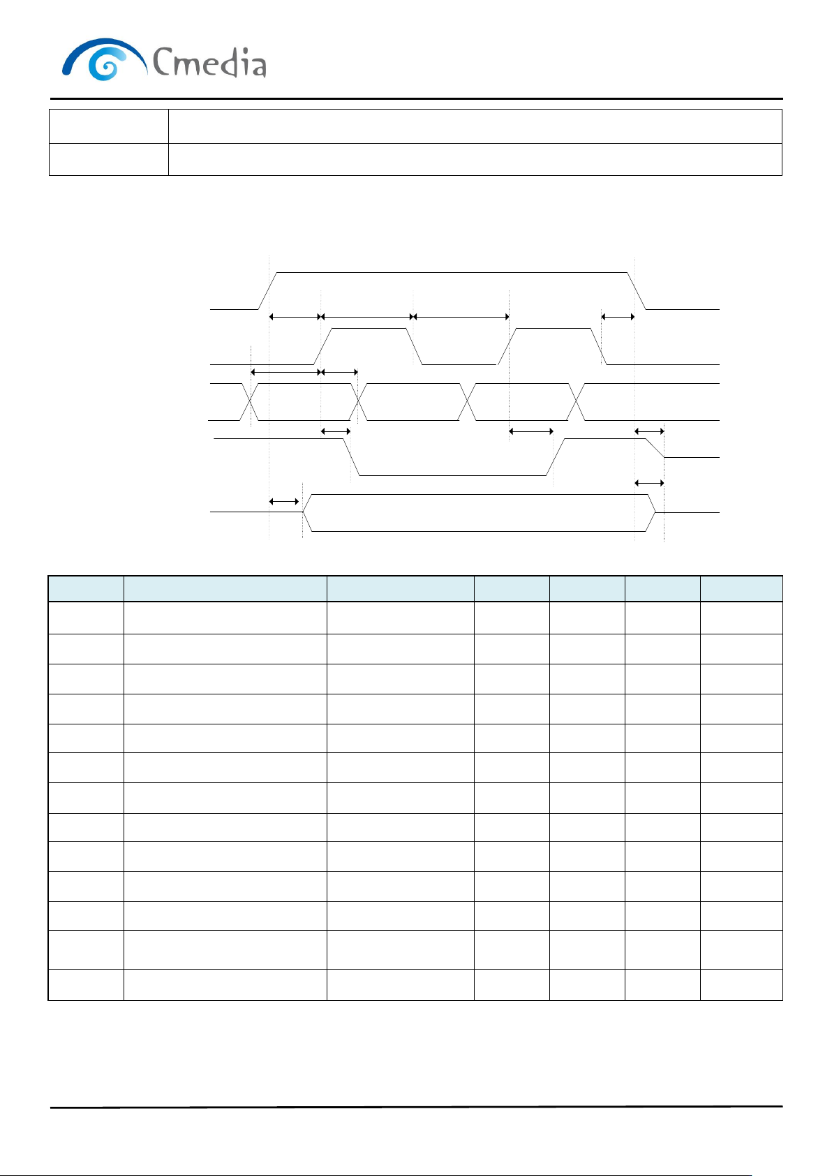
7.1.4 EEPROM SPI interface timing information
CS
SK
DI
DO(READ)
DO(PROG)
t
SV
t
PD1
t
DF
t
DF
t
CSH
t
SKL
t
SKH
t
CSS
t
PD0
t
DIH
t
DIS
STATUS VALID
Symbol
Parameter
Test Condition*
Min
Typ
Max
Units
f
SK
SK Clock Frequency
2.7V<=Vcc<=5.5V
0
-
200
KHz
t
SKH
SK High Time
2.7V<=Vcc<=5.5V
250
-
-
ns
t
SKL
SK Low Time
2.7V<=Vcc<=5.5V
250
-
-
ns
t
CS
Minimum CS Low Time
2.7V<=Vcc<=5.5V
250
-
-
ns
t
CSS
CS Setup Time
2.7V<=Vcc<=5.5V
50
-
-
ns
t
DIS
DI Setup Time
2.7V<=Vcc<=5.5V
100
-
-
ns
t
CSH
CS Hold Time
2.7V<=Vcc<=5.5V
0
-
-
ns
t
DIH
DI Hold Time
2.7V<=Vcc<=5.5V
100
-
-
ns
t
PD1
Output Delay to"1"
2.7V<=Vcc<=5.5V
-
-
250
ns
t
PD0
Output Delay to"0"
2.7V<=Vcc<=5.5V
-
-
250
ns
t
SV
CS to Status Valid
2.7V<=Vcc<=5.5V
-
-
250
ns
t
DF
CS to DO in High
Impedance
2.7V<=Vcc<=5.5V
-
-
100
ns
t
WP
Write Cycle Time
4.5V<=Vcc<=5.5V
0.1
3
10
ms
* based on ATMEL 93C46 EEPROM data
CM108B
USB Audio Single Chip
Datasheet Revision: 1.11 www.cmedia.com.tw
Page 15 / 24 Copyright© C-Media Electronics Inc.
7.2 Jumper pins and mode setting:
The CM108B can be configured via several jumper pins. These jumper pin settings affect both USB descriptors and
USB audio topology.
7.2.1 Mode pin and msel pin
If the MODE pin is pushed up to 3.3V (speaker mode), a playback-only function is activated and no recording function
is declared to the host. At this setting, the MSEL pin is ignored and only one input terminal, one output terminal and
one feature unit is declared in the USB audio topology.
If the MODE pin is pulled low (headset mode), a full-duplex playback and recording function is reported to the host.
The MSEL pin setting activates one mixer unit and one feature unit.
When MSEL = 1, the mixer is enabled (AA-path enabled), but with default mute setting
When MSEL = 0, the mixer is disabled (AA-path disabled)
The above USB audio topology (7.1.4) is an example of headset mode with enabled mixer.
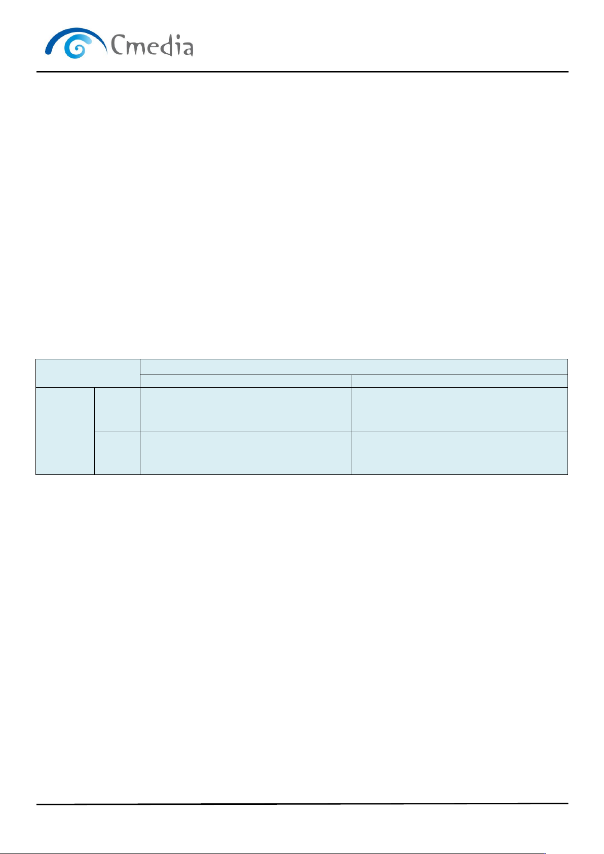
7.2.2 Mode pin and pwrsel pin
The PWRSEL pin affects the power configuration of the CM108B. Together with the MODE pin, there are a total of 4
programmable combinations.
Combinations
MODE
3.3V
GND
PWRSEL
3.3V
Speaker mode:
Playback only
(100mA self-powered)
Headset mode:
Playback and recording
(100mA Bus-powered)
GND
Speaker mode:
Playback only
(500mA Bus-powered)
Headset mode:
Playback and recording
(500mA Bus-powered)
USB Audio Topology Diagram