C371347_139780418F8DFE40697A24CD62AD2CE5.pdf - 第5页
CM108B USB Audio Single C hip Datasheet Revision: 1.11 www .cmedia.com.tw P age 5 / 24 Copyright© C -Media Elect ronics Inc. Embedded 16-bit ADC i nput with mi crophone b oost Embedded power-on res et block Embedde…

CM108B
USB Audio Single Chip
Datasheet Revision: 1.11 www.cmedia.com.tw
Page 4 / 24 Copyright© C-Media Electronics Inc.
1 Description and overview
The CM108B is a highly integrated single-chip USB audio solution. All essential analog modules are embedded in the
CM108B, including dual DAC and earphone driver, ADC, microphone booster, PLL, regulator and USB transceiver
modules. It is perfectly suited to USB headset, USB earphone or USB audio-interface box applications. As well, many
features are programmable with jumper pins or by external EEPROM.
The CM108B can connect to an external codec or audio DSP via I2S pins for further processing. Plus, 3 GPIO pins can
be accessed with customer application software for additional value-adding applications. In addition, audio
adjustments can be easily controlled via specific HID compliant volume control pins. Many features are
programmable with jumper pins or external EEPROM. Vendors can customize unique USB VID/PID/Product
String/Manufacture String and max/min/initial volumes to EEPROM. The CM108B also comes with an anti-pop noise
circuits design and internal oscillator which can operate without an external crystal oscillator.
2 Ordering information
Model No.
Package
Operating Ambient
Temperature
Supply Range
CM108B
48-pin LQFP, 7mm × 7mm × 1.4mm
(plastic)
-20°C to +70°C
DVdd = 5V, AVdd = 5V
3 Features
Supports USB 2.0 full speed operation
Compliant with USB audio device class specification 1.0
Supports USB suspend/resume modes and remote wakeup with volume control pins
On-chip oscillator that provides reference sources for PLL and embedded USB transceiver
Support Xear
TM
audio driver for multimedia sound effects in Windows OS, for further information please refer to
CM108B Xear
TM
Audio Center Driver User’s Manual
Jumper pin for speaker mode (playback only) or headset mode (playback plus recording)
For headset mode, USB audio function topology has 2 input terminals, 2 output terminals, 1 mixer unit, 1 selector
unit and 3 feature units
Jumper pin allows for mixer unit enable/disable when in headset mode
For speaker mode, the USB audio topology has 1 input terminal, 1 output terminal and 1 feature unit
Supports one control endpoint, one isochroous OUT endpoint, one isochroous IN endpoint, and one interrupt IN
endpoint
Alternate zero bandwidth setting for releasing playback bandwidth on USB Bus when device is inactive
Anti-pop noise design for device plugged and vice-versa, while A-A path is off
Supports AES/EBU, IEC60958, S/PDIF consumer formats for stereo PCM data at S/PDIF output
Volume up, volume down, and playback mute pins support USB HID for host control synchronization
Record mute pin with LED indicator for record mute status
Includes external EEPROM Interface for Vendor Specific USB VID, PID, Product String, Manufacture String, and
max/min/initial volumes
3 GPIO pins with read/write via HID interface
Jumper pin to set the power mode (100mA or 500mA, Bus-powered or self-powered)
Isochronous transfer uses adaptive mode with internal PLL for synchronization
48K/44.1KHz sampling rate for both playback and recording
Soft mute function

CM108B
USB Audio Single Chip
Datasheet Revision: 1.11 www.cmedia.com.tw
Page 5 / 24 Copyright© C-Media Electronics Inc.
Embedded 16-bit ADC input with microphone boost
Embedded power-on reset block
Embedded 5V to 3.6V/3.3V/1.8V regulators for single external 5V power
48-pin LQFP package
CM108B
USB Audio Single Chip
Datasheet Revision: 1.11 www.cmedia.com.tw
Page 6 / 24 Copyright© C-Media Electronics Inc.
4 Pin descriptions
4.1 Pin assignment by pin number
Pin #
Signal Name
Pin #
Signal Name
Pin #
Signal Name
Pin #
Signal Name
1
SPDIFO
13
GPIO3
25
VBIAS
37
AREG36
2
DR
14
DVSS
26
VREF
38
MSEL
3
DW
15
GPIO4
27
MICIN
39
VOLUP
4
SK
16
SDIN
28
N.C.
40
PDSW
5
CS
17
ADSCLS
29
AVDD
41
USBDP
6
MUTER
18
MUTEP
30
LOL
42
USBDM
7
PWRSEL
19
ADLRCK
31
LOBS
43
GPIO1
8
DREG18
20
ADMCLK
32
LOR
44
SDOUT
9
DREG33
21
LEDR
33
AVSS
45
DAMCLK
10
MODE
22
ADSEL
34
AVDD
46
DALRCK
11
N.C.
23
TEST
35
DVDD
47
DASCLK
12
LEDO
24
AVSS
36
DVSS
48
VOLDN
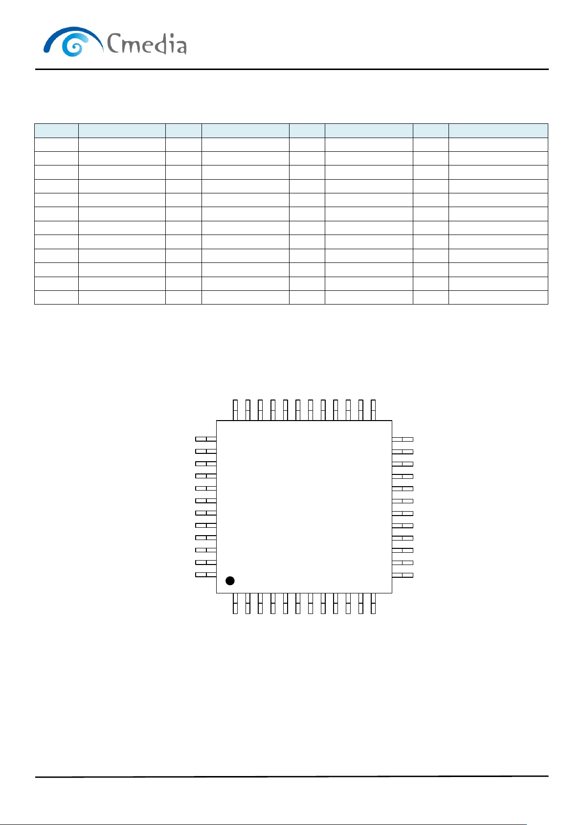
4.2 Pin-out diagram
CM108B
LQFP-48
1
2
3
4
5
6
7
8
9
10
11
12
SPDIFO
DR
DW
SK
CS
MUTER
PWRSEL
DREG18
DREG33
MODE
N.C.
LEDO
36
35
34
33
32
31
30
29
28
27
26
25
24
23
22
21
20
19
18
17
16
15
14
13
AVSS
TEST
ADSEL
LEDR
ADMCLK
ADLRCK
MUTEP
ADSCLK
SDIN
GPIO4
DVSS
GPIO3
37
38
39
40
41
42
43
44
45
46
47
48
AREG36
MSEL
VOLUP
PDSW
USBDP
USBDM
GPIO1
SDOUT
DAMCLK
DALRCK
DASCLK
VOLDN
DVSS
DVDD
AVDD
AVSS
LOR
LOBS
LOL
AVDD
N.C.
MICIN
VREF
VBIAS
Pin Assignments (top view)