CP43维护手册.pdf.pdf - 第101页
10 – 1 V ersion 7.0 Chapter 10 Cam Box 10. Cam Box The cam box, located on the upper part of the CP IV -3, consists of two camshafts, nine cams, one index cam, one cylinder cam and a main motor which drives the system. T…
Chapter 9 XY Table
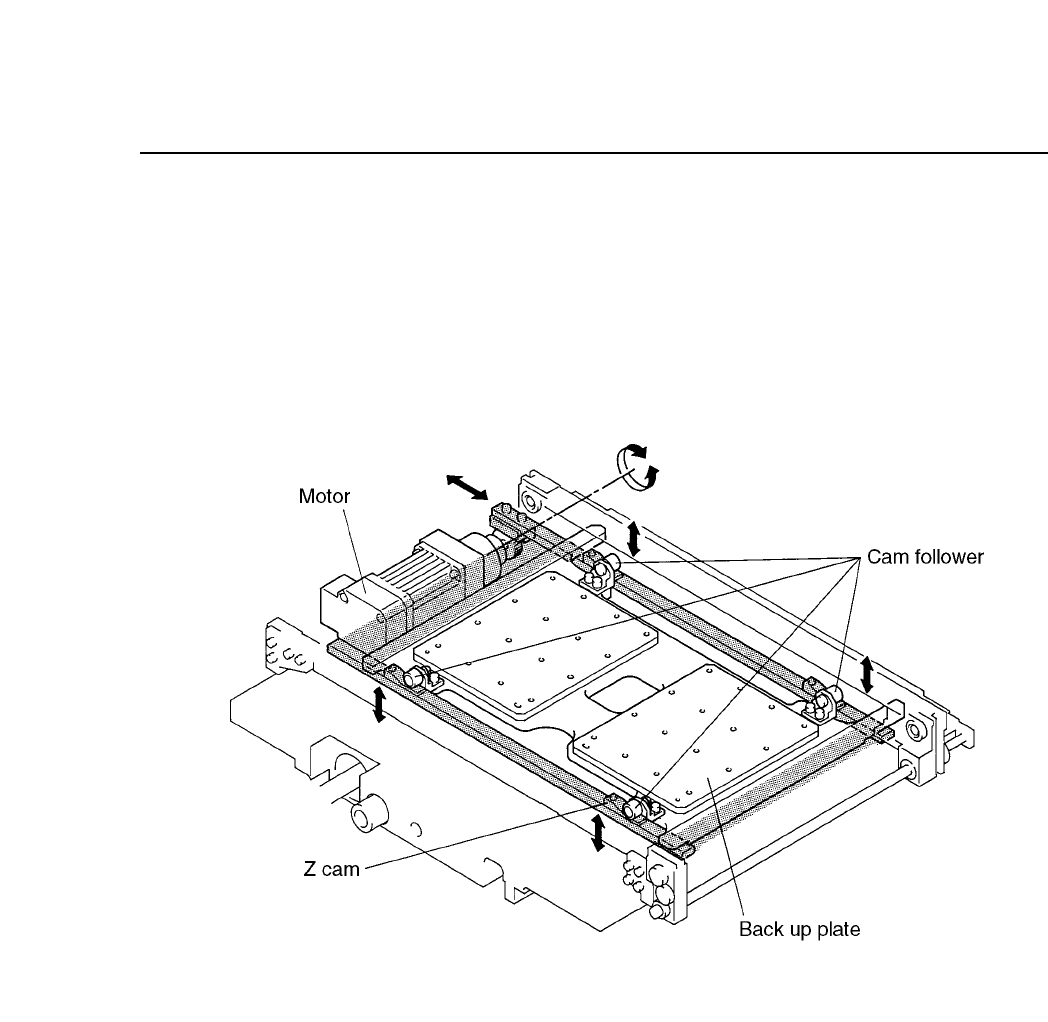
As shown in the configuration of the automatic table height changer
(figure 9-2), the Z axis motor rotates to move the rack and pinion system,
moving the LM guides left and right. On the LM guides there are four fixed Z
cams. As the LM guides move, the cam followers slide over the Z cam and this
makes the back-up plate move up and down.
Fig. 9-2 Automatic Table Height Changer Configuration
9 – 2
Version 7.0
CP IV-3 Maintenance
10 – 1
Version 7.0
Chapter 10 Cam Box
10.Cam Box
The cam box, located on the upper part of the CP IV-3, consists of two
camshafts, nine cams, one index cam, one cylinder cam and a main motor
which drives the system. This mechanism drives the placing head and feeder
at stations 1, 3, 6, 7 and 11.
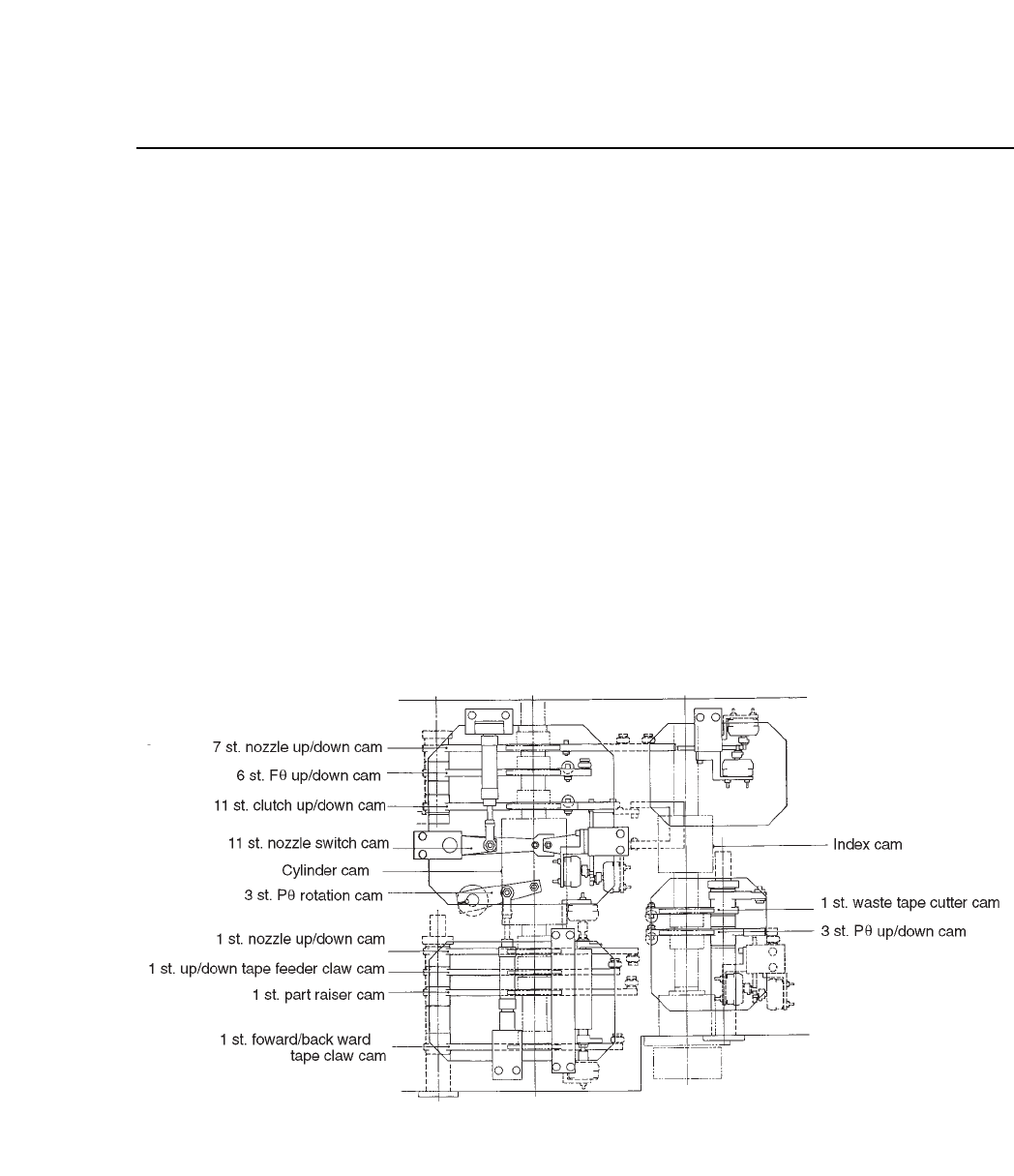
10.1Schematic Diagram and Parts of the Cam
Refer to the schematic of the inside of the cam box (figure 10-1) below.
This diagram is an overhead view oriented from the rear of the machine.
There is a seal attached to the cam lever. However, there is no seal
attached to the index cam or the cylinder cam. The labels, except for
parenthetical comments, are as listed on the machine itself.
Fig. 10-1 Cam Schematic Diagram
CP IV-3 Maintenance
Chapter 10 Cam Box
10.2The Workings of the Cam
The cam box consists of nine cams, one index cam and one cylinder cam.
The purpose of these items are explained here.
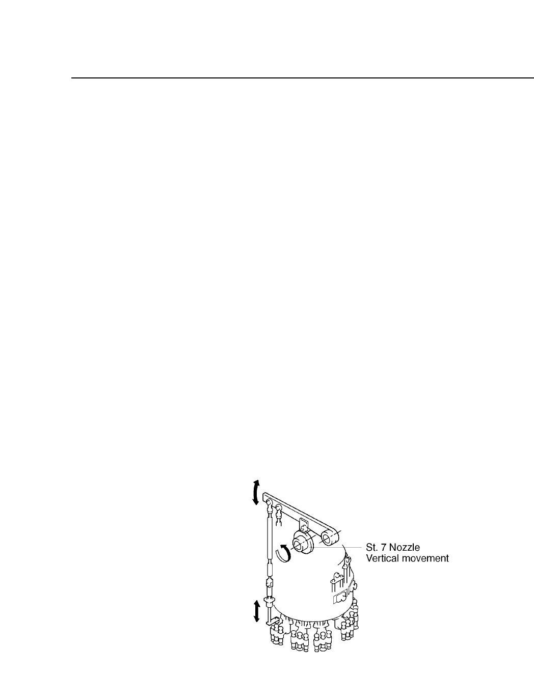
10.2.1The Nine Cams
The nine cams are used in the operation of the feeders and placing
heads.
Five cams operate at station 1 controlling the following areas of
operation:
• Feeder tape advance/retract
• Feeder tape advance
• Feeder parts push-up
• End tape cut
• Vertical movement of the nozzle
The remaining four each operate one of these functions:
• Pre-theta (vertical movement) at station 3
• Fine-theta (vertical movement) at station 6
• Nozzle (vertical movement) at station 7
• Nozzle changeover (vertical movement) at station 11
Fig. 10-2 The Operation of the 9 Cams
The cam lever is connected to the rod. The rod is connected to the
feeder or the placing head.
10 – 2
Version 7.0
CP IV-3 Maintenance