CP43维护手册.pdf.pdf - 第118页
Chapter 1 1 Servo Amplifiers 1 1.2 Display During Servo Amp Malfunction Over-curr ent (all axes) Circuit pr otector tripped (all axes) Regenerative trouble (all axes) Over-voltage (all axes) Over-speed (all axes) V oltag…
11 – 1
Version 7.0
Chapter 11 Servo Amplifiers
11. Servo Amplifiers
There are six types of servo amplifiers on this machine. Each servo amplifier is
listed below.
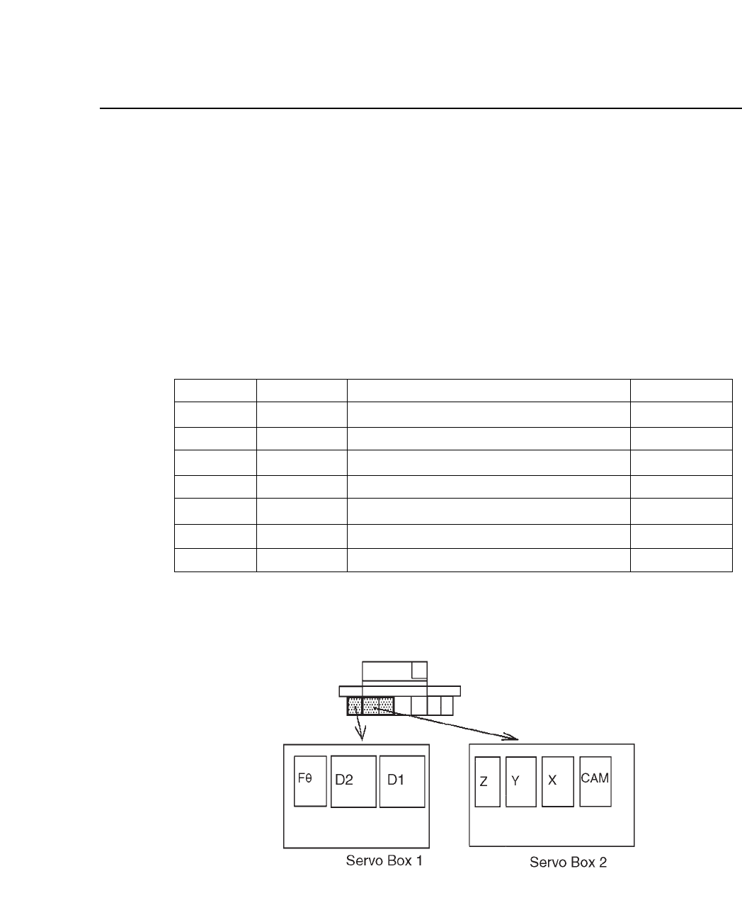
11.1Servo Amplifier Types and Locations
The table below lists the the part number, nomenclature, and location of
each axis’ servo.
Table 11-1 Servo Amplifier Types
Fig. 11-1 Servo Amplifier Locations
F axis
D1 axis
D2 axis
Z axis
Y axis
X axis
CAM axis
Axis Assy. No.
Location
SAA-1110
SAA-1180
SAA-1170
SAA-1160
SAA-1100
Servo amp CACR-SR03BC1KSY264
Servo amp CACR-SR44BC1CSY349
Servo amp CACR-SR44BC1CCY349
Servo amp CACR-SR01AC1ERY102
Servo amp CACR-SR05BC1ESY278
Servo amp CACR-SR10BC1ESY262
Servo amp CACR-SR30BC1ASFY244
Servo box 1
Servo box 1
Servo box 1
Servo box 2
Servo box 2
Servo box 2
Servo box 2
Code
θ
θ
θ
CP IV-3 Maintenance
Chapter 11 Servo Amplifiers
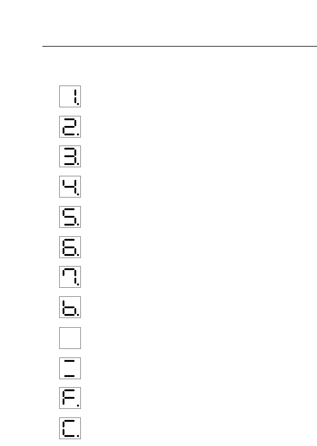
11.2Display During Servo Amp Malfunction
Over-current (all axes)
Circuit protector tripped (all axes)
Regenerative trouble (all axes)
Over-voltage (all axes)
Over-speed (all axes)
Voltage drop (all axes)
Overload (all axes)
A/D error (all axes)
CPU error (this display is for Fθ, cam, D, X, Y axes)
CPU error (this display is for Z axis)
Open phase (no display for Z axis)
Overrun protection (all axes)
11 – 2
Version 7.0
CP IV-3 Maintenance
12 – 1
Version 7.0
Chapter 12 VME Boards
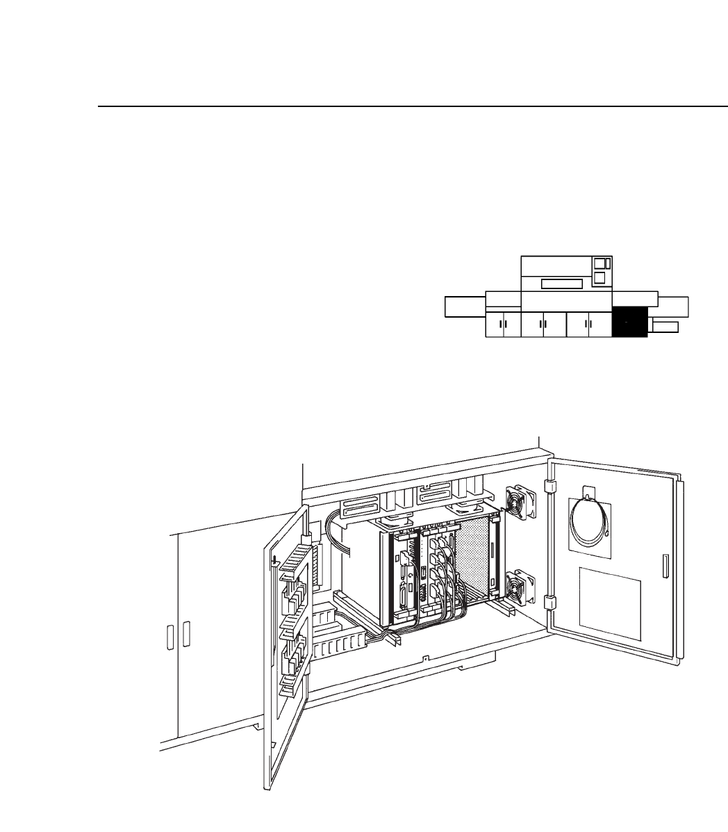
12.VME Boards
This chapter describes the control boards used with the CP IV-3.
As shown in the illustration below,
the control boards are in the VME
rack in the control box on the lower
right-hand side of the machine.
Fig. 12-1 Control Box Location and Detailed View
CP IV-3 Maintenance