CP43维护手册.pdf.pdf - 第122页
Chapter 12 VME Boards 12.1 Control Box 2 Optional Boards • Conveyor width control servo boar d VM1530 (Optional) This is an additional board r equir ed when the HELPS manufacturing support system is used. It controls con…

12 – 3
Version 7.0
Chapter 12 VME Boards
(b) Console board AVME ~ 311F
This board controls the color display on the operation panel.
(c) Vision processing board VM4400
This board controls vision processing of parts that are inspected before
placement.
(d) Servo board IS70B
This board controls the servo motors for the machine axes. The speed and
positioning of the C and Fθ axes are controlled with this board.
(e) Servo board IS70B
This board controls the servo motors for the machine axes. The speed and
positioning of the X, Y, and Z axes are controlled with this board.
(f) Servo board IS70B
This board controls the servo motors for the machine axes. The speed and
positioning of the D1 and D2 axes are controlled with this board.
(g) VME interface board MX100CP91D
This board transmits signals from sensors and switches to the CPU and
uses signals from the CPU to control the relay valve, etc. This board has a
direct cable to the I/O in control box 1.
(h) SCSI Vision Processing External Memory Board
FSC-30A02 and FSC-30C
This board contains necessary data pertaining to nozzles and picking parts.
This memory is saved to the board and backed up by a battery so turning
the machine on or off, or performing reset start will not have any effect on
this memory.
(i) MP board VM1932
This board is connected to a battery which serves as a backup to preserve
the RAM memory when the machine power is cut. If this battery goes dead
and the machine power is cut the memory will be erased.
When the machine control system comes with a memory card, the card
must be inserted here.
This board goes into the the farthest right slot of the board rack.
Note: For further information on changing the memory card see Chapter 16,
Upgrading the Software.
CP IV-3 Maintenance
Chapter 12 VME Boards
12.1Control Box 2 Optional Boards
• Conveyor width control servo board VM1530 (Optional)
This is an additional board required when the HELPS manufacturing
support system is used. It controls conveyor width.
• 4 channel communication board VME070 (Optional)
This is an additional board required when the HELPS manufacturing
support system is used. It carries out the communication between
LMS and the bar code reader or pattern code reade and the Handy
Terminal.
12.2Other Controls for Control Box 2
• Loader programmable controller MX100
Programmable controller for the board transport loader system.
12.3Control Box 1
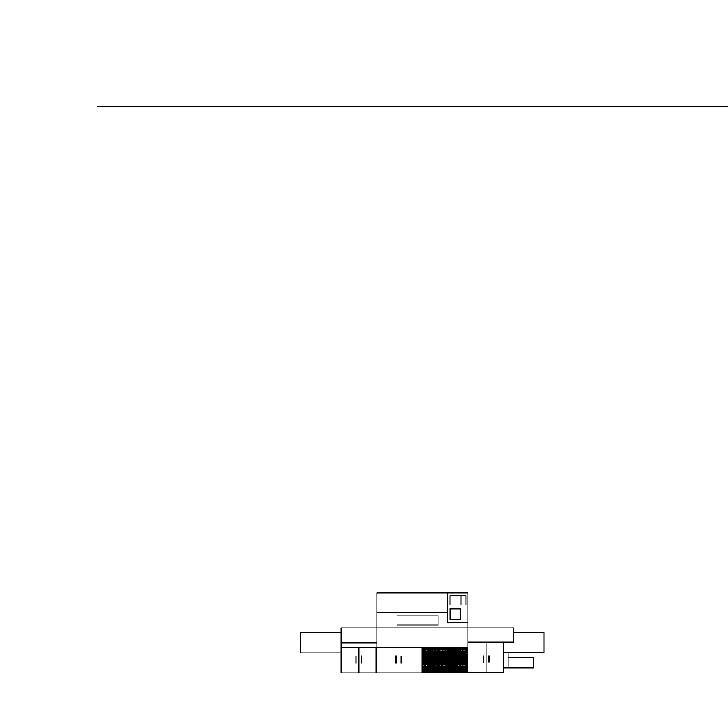
The direct I/O is located inside control box 1.
Fig. 12-3 Direct I/O Location
• Direct I/O board
The I/O board receives input from sensors and switches on the
machine and sends the signals on to the CPU. In addition, this board
receives the outputs from the CPU and uses them to control the
solenoids and relays. This direct I/O board is directly connected to
the VME Interface (MX100CP91) in the VME board in control box 2.
12 – 4
Version 7.0
CP IV-3 Maintenance

13 – 1
Version 7.0
Chapter 13 Changeover
13.Changeover
This chapter describes changeover procedures for the CP IV-2. These include
the following:
• program changeover
• XY table guide rail width changeover
• in and out conveyor width changeover
• tape feeder changeover
• back-up pin position changeover
• board pin pitch changeover
• pin changeover (when changing pin diameter)
13.1Program Changeover
When the next production program already exists in the machine, press
[PROGRAM], [CHANGE], [# of the program] and [CR]. This will move
the program from the background to the foreground.
When the next program does not exist in the machine, transmit it from
MCS to the background of the machine. Once it is in the machine's
background, press [PROGRAM], [CHANGE], [# of the program], and
[CR] to move it from the background to the foreground.
13.2Conveyor Width Changeover
Width changeover for the XY table guide rail, in conveyor and out
conveyor is performed in one operation. This operation is performed
according to the following procedure:
(1) Press [LOADER], [LOADING PSTN] and [START].
The XY table will line up with the in and out conveyors.
(2) Press [LIFTER ▲]. The XY table is raised to the same height as the
OUT conveyor.
(3) Turn the conveyor width changeover handle on the out conveyor to
align the conveyor width to that of the board. Leave 0.5 ~ 1.0 mm so
that the board is not squeezed in too tightly.
CP IV-3 Maintenance