CP43维护手册.pdf.pdf - 第125页
13 – 3 V ersion 7.0 Chapter 13 Changeover 13.6 Reference Pin Changeover (When Changing Pin Diameter) When replacing pins, never loosen the securing bolt on the pin block. If this block is loosened, the XO/YO Proper value…
Chapter 13 Changeover
(4) Press [LIFTER ▼]. The XY table is lowered to the height for placing.
Note: Be sure to check the position of the back-up pins after a width change.
The back rails may collide with the pins resulting in damage when the
lifter table is lowered.
13.3Tape Feeder Changeover
Place the tape feeders on the device table as indicated by the program.
13.4Back-up Pin Position Changeover
(1) Press [LOADER], [LOADING PSTN] and [START].
The Y table will line up with the in and out conveyors..
(2) Press [LIFTER ▲]. The XY table is raised to the same height as the
OUT conveyor.
(3) Change the position of the back-up pins.
(4) Confirm that the the back-up pins will not collide with the guide rail
when the XY table is lowered. If collision is possible, move the back-
up pins.
(5) Press [LIFTER ▼]. The XY table is lowered to the height for placing.
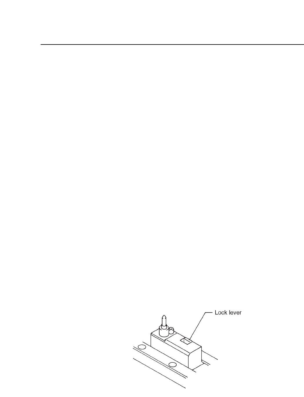
13.5Board Pin Pitch Changeover
Push back the lock lever and adjust the position of the pin pitch holder to
the pin pitch of the board.
Fig. 13-1 XY Table
13 – 2
Version 7.0
CP IV-3 Maintenance
13 – 3
Version 7.0
Chapter 13 Changeover
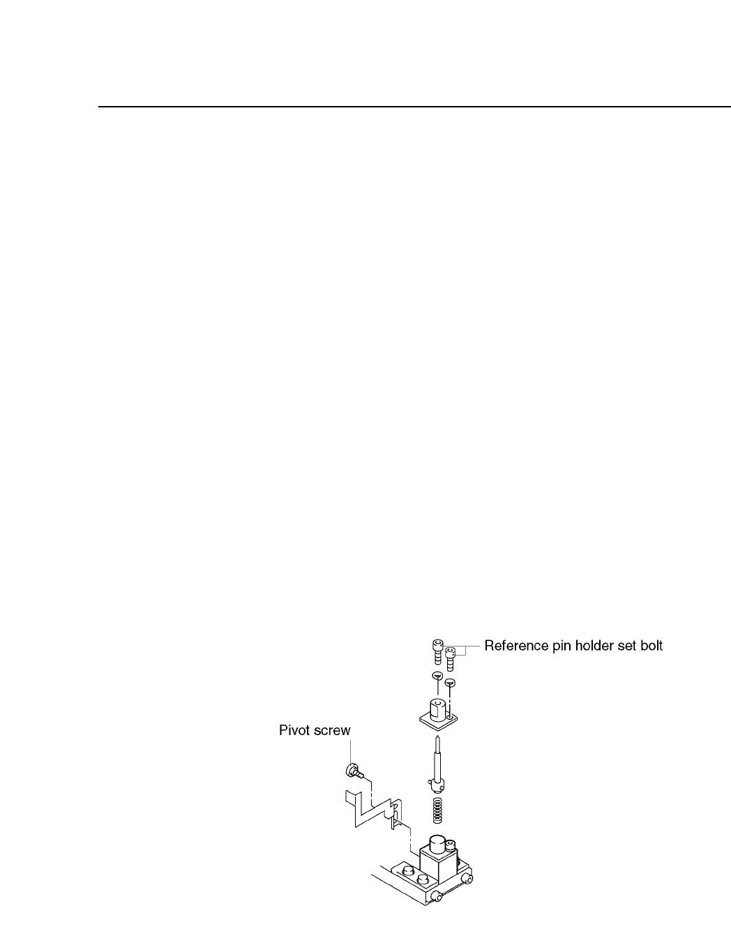
13.6Reference Pin Changeover (When Changing Pin Diameter)
When replacing pins, never loosen the securing bolt on the pin block. If
this block is loosened, the XO/YO Proper values will change and part
placement will be misaligned. Follow the procedure below to change
pins.
(1) Press [LOADER], [LOADING PSTN] and [START].
The XY table will line up with the in and out conveyors.
(2) Press [LIFTER ▲]. The XY table is raised to the same height as the
OUT conveyor.
(3) Unscrew the pivot pin.
(4) Unscrew the pin holder set bolt.
(5) Remove the pin and holder from the block. Be careful that the spring
loaded beneath the pin does not shoot out.
(6) Change the pins.
(7) After changing the pins, check to see if the spring pin which is
attached to the bottom of the reference pin is inserted in the (A) hole
of the dog. Repeat the steps given thus far in reverse order to reattach
the pin.
(8) Press [LIFTER ▼]. The XY table is lowered to the height for placing.
Fig. 13-2 Reference Pin Unit
CP IV-3 Maintenance
Chapter 13 Changeover
13.7Follow-up Pin Changeover (When Changing Pin Diameter)
The procedures for changing the attached pin are the same as when
changing the reference pin, except there is no dog for the attached pin.
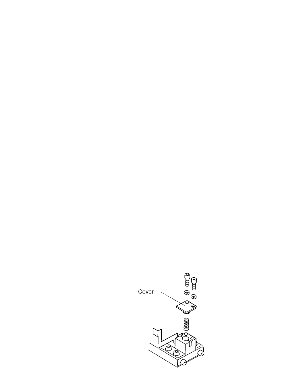
13.8Fiducial Mark Settings
When the reference pin and follow-up pins are not used, and the machine
only uses the fiducial marks as a reference, follow the steps listed below.
(1) Select [LOADER], [LOADING POSTN], and press the START button
to move the XY table to the loading position.
(2) Press [LIFTER ▲] and the XY table is raised to the same height as the
in and out conveyors.
(3) Unscrew the pivot pin.
(4) Unscrew the pin holder set.
(5) Remove the pin and holder from the block. Be careful that the spring
loaded beneath the pin does not shoot out.
(6) While the spring is in the block, attach the cover to the reference pin
block. While the dog is attached, check to see if the spring pint that is
attached to the cover, is in the hole of the dog. Attach the cover.
(7) It is not necessary to remove the follow-up pin. The block should be
set for each board to be produced.
Fig. 13-3 Fiducial Mark Reference
13 – 4
Version 7.0
CP IV-3 Maintenance