CP43维护手册.pdf.pdf - 第130页
Chapter 14 Replacing Consumable Parts 14.5 V alve Replacement During automatic production, a nozzle sometimes pr oduces r epeated errors. If the cause appears to be blockage or bends in the nozzle, the spool valve may be…
14 – 3
Version 7.0
Chapter 14 Replacing Consumable Parts
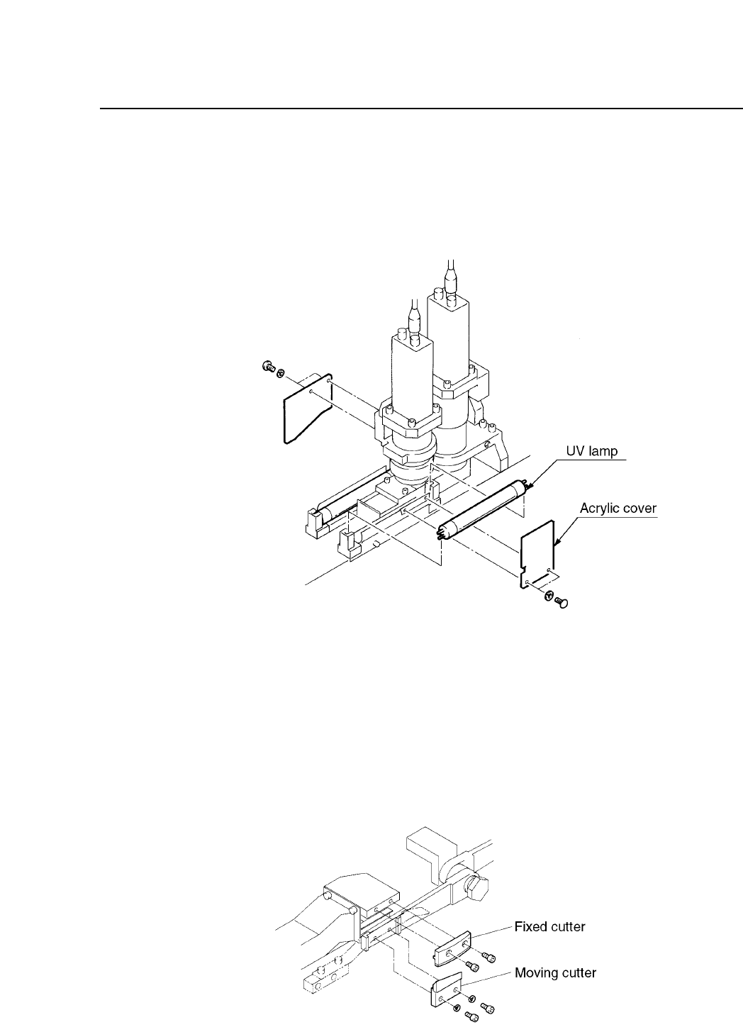
14.3Vision Processing UV Lamp Replacement
To replace the vision processing UV lamp, first remove the brown plastic
cover. Next remove the UV lamp. Do not touch the bulb with your bare
hands, as traces of oil will be left on the bulb, which will shorten its life.
Fig. 14-2 UV Lamp Assembly
14.4Replacing the Waste Tape Cutter
If waste tape is not being cut properly, tape feed may be slowed or tape
may get backed up. In such cases, replace the waste tape cutter.
Remove the cutter by unscrewing the two bolts on the moving and the
fixed cutter. Put in a new cutter and re-tighten the two bolts.
Fig.14-3 Tape Leaf Cutter Mechanism Bolts
CP IV-3 Maintenance
Chapter 14 Replacing Consumable Parts
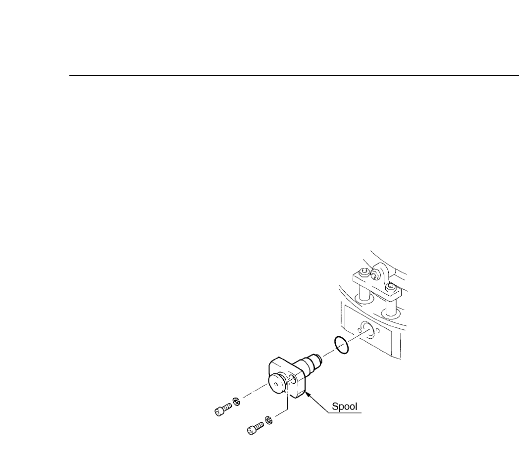
14.5Valve Replacement
During automatic production, a nozzle sometimes produces repeated
errors. If the cause appears to be blockage or bends in the nozzle, the
spool valve may be deformed or O ring damage may have caused a
vacuum leak. The O ring is attached to the spool valve. Replace the spool
valve if necessary.
To remove the spool valve or O ring, unscrew the two bolts shown below.
Be careful not to break the O ring, as it is thin and fragile.
Fig.14-4 Spool Valve Assembly
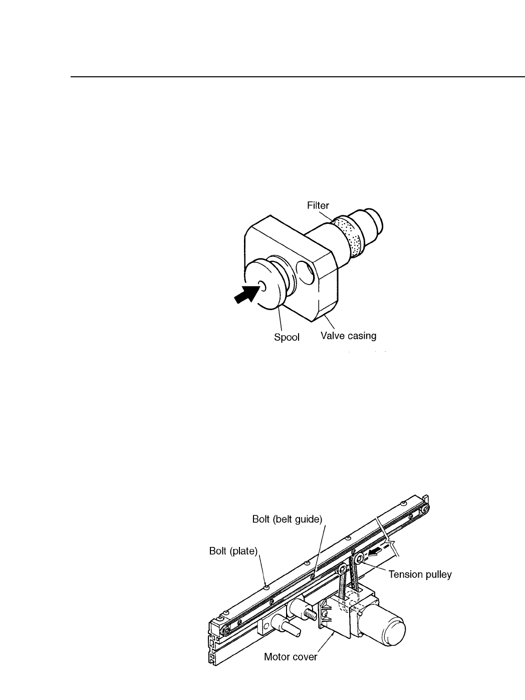
14.6Changing the Mechanical Valve Filter
It is necessary to periodically clean the head spools (refer to section 15.10
for further details). When the spools are being cleaned, if the mechanical
valve filter is found to be dirty or damaged, promptly replace it with a
new one.
(1) Remove the filter from the valve casing. Tweezers can be used to
remove the filter.
Note: Ensure no refuse from the filter remains in the valve.
(2) Clear any refuse from the spool hole (indicated by the arrow in the
diagram below) using an air gun.
(3) Insert the new filter on the valve casing, ensuring the filter remains
round in shape.
14 – 4
Version 8.0
CP IV-3 Maintenance
14 – 5
Version 8.0
Chapter 14 Replacing Consumable Parts
(4) Make sure the new filter does not protrude from its position on the
valve casing. Use your finger to push the filter into place if it is
protruding from the valve casing. The mechanical valve unit can be
replaced once this is complete.
Fig. 14-5 Mechanical Valve Unit
14.7Conveyor Belt Replacement
The CP IV-2 employs a rubber T-type conveyor belt. The procedures for
changing the conveyor belt are listed on the following page.
Fig. 14-6 Conveyor Belt Replacement
CP IV-3 Maintenance