CP43维护手册.pdf.pdf - 第138页
Chapter 14 Replacing Consumable Parts (3) Hang the belt. Check to see that the value of the tension is within the specified range. If it is not in the range, remove the belt, and rehang the belt so that ther e is a 0.1 m…
14 – 11
Version 7.0
Chapter 14 Replacing Consumable Parts
The following procedures should be followed when removing and
attaching the pump. The procedures listed below enable the
adjustment for the belt tension to be done with ease.
When removing the pump, follow the procedures below.
(1) Remove the belt from the pulley.
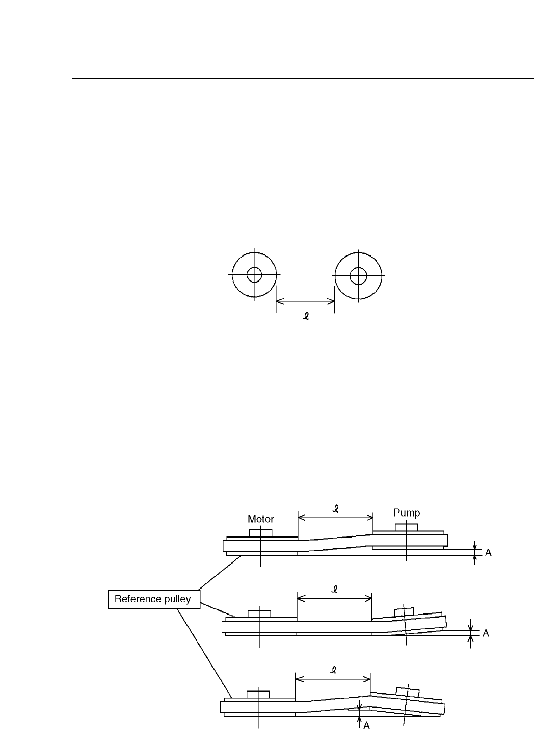
(2) Using a caliper measure the distance between the pulley and
the motor axis. Record this distance.
Fig. 14-9 Distance between the Axes
(3) Remove the pump.
When attaching the pump back follow the procedures below.
(1) Without moving from its position, place the pump on the base.
(2) Temporarily stop the pump, and adjust the alignment
according to the measurements that were recorded previously
for the distance between the axes. The permissible amount of
leeway for the alignment should be no greater than 0.3. mm.
Fig. 14-10 Adjusting the Alignment of the Axes
CP IV-3 Maintenance
Chapter 14 Replacing Consumable Parts
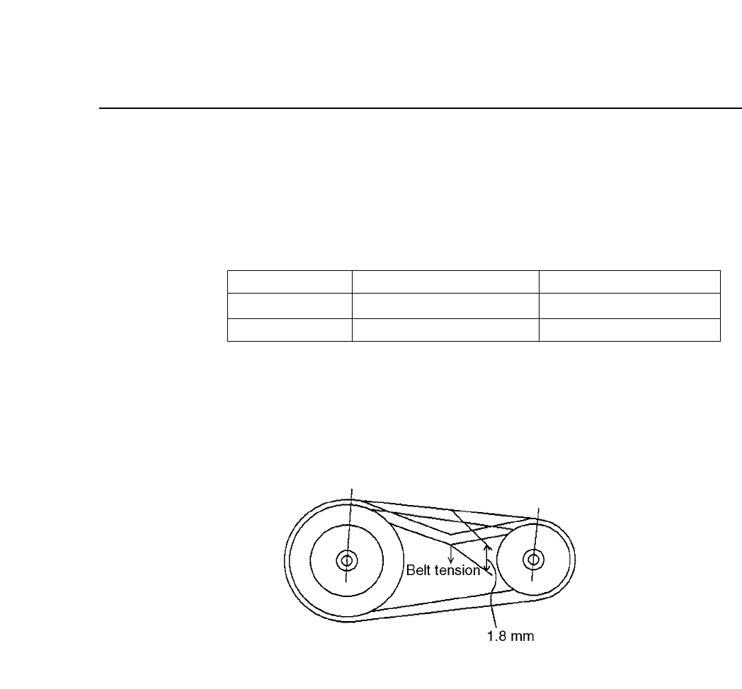
(3) Hang the belt. Check to see that the value of the tension is
within the specified range. If it is not in the range, remove the
belt, and rehang the belt so that there is a 0.1 mm leeway for
each belt for the l dimension.
Table 14-4 Belt Tension
Note: The tension meter that is used is the Gates Polyflex Tension
Meter-7M.
Fig. 14-11 Belt Tension
Slack - Load
Tension Meter
In Use
0.50 - 0.60 kg : 1.8 mm
28 - 34 lb
New Belt
0.38 - 0.46 kg : 1.8 mm
20 - 26 lb
14 – 12
Version 7.0
CP IV-3 Maintenance
15 – 1
Version 7.0
Chapter 15 Routine Inspections and Maintenance
15.Routine Inspections and Maintenance
This chapter describes parts of the machine that must be cleaned relatively
frequently. If cleaning is neglected, machine operation will be impaired and
placing performance will drop.
15.1Cleaning the Nozzles
The vacuum nozzles draw in air. Nozzle blockage occurs when particles
of dust, glue, and solder paste are drawn in and solidify.
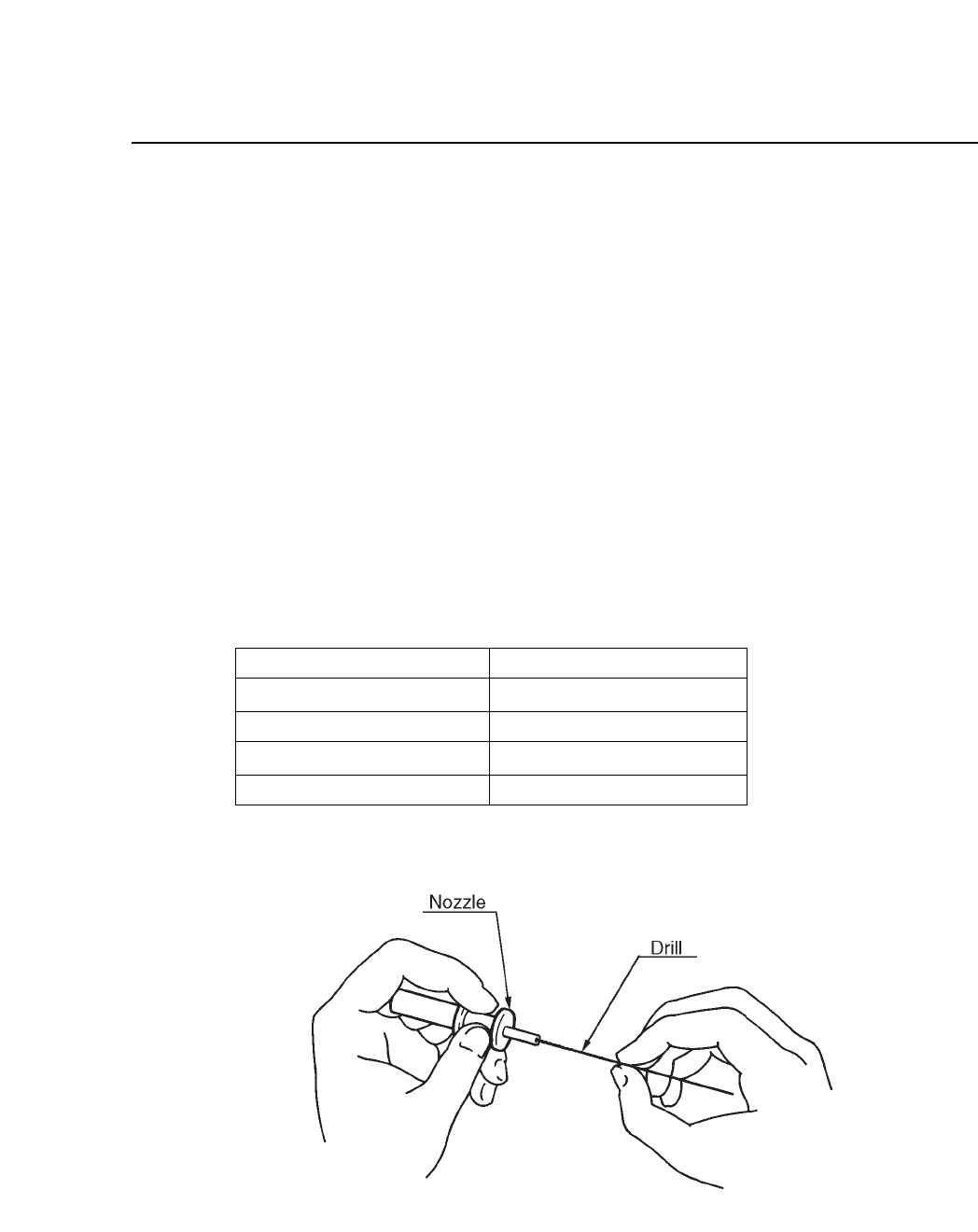
If this blockage is not corrected, pick-up errors will occur and placing
performance will drop. If a certain nozzle consistently causes pickup
errors, clean it out by inserting and turning a drill bit as shown in the
illustration below.
Table 15-1 Nozzle Diameters
Fig. 15-1 Cleaning Nozzle with Drill Bit
0.7 mm
1.0 mm
1.3 mm
1.8 mm
Outer diameter of nozzle
Inner diameter of nozzle
0.4 mm
0.7 mm
1.0 mm
1.45 mm
CP IV-3 Maintenance