CP43维护手册.pdf.pdf - 第38页
4 – 2 V ersion 1.0 Chapter 4 Functions of the Parts 4.2 Placing System • Cam Box The cam box, which is located in the upper part of the machine, consists of the cam axis motor , cams, cam axes, cam levers, rotary solenoi…
Chapter 4 Functions of the Parts
4. Functions of the Parts
Herein is an explanation of the function of each part.
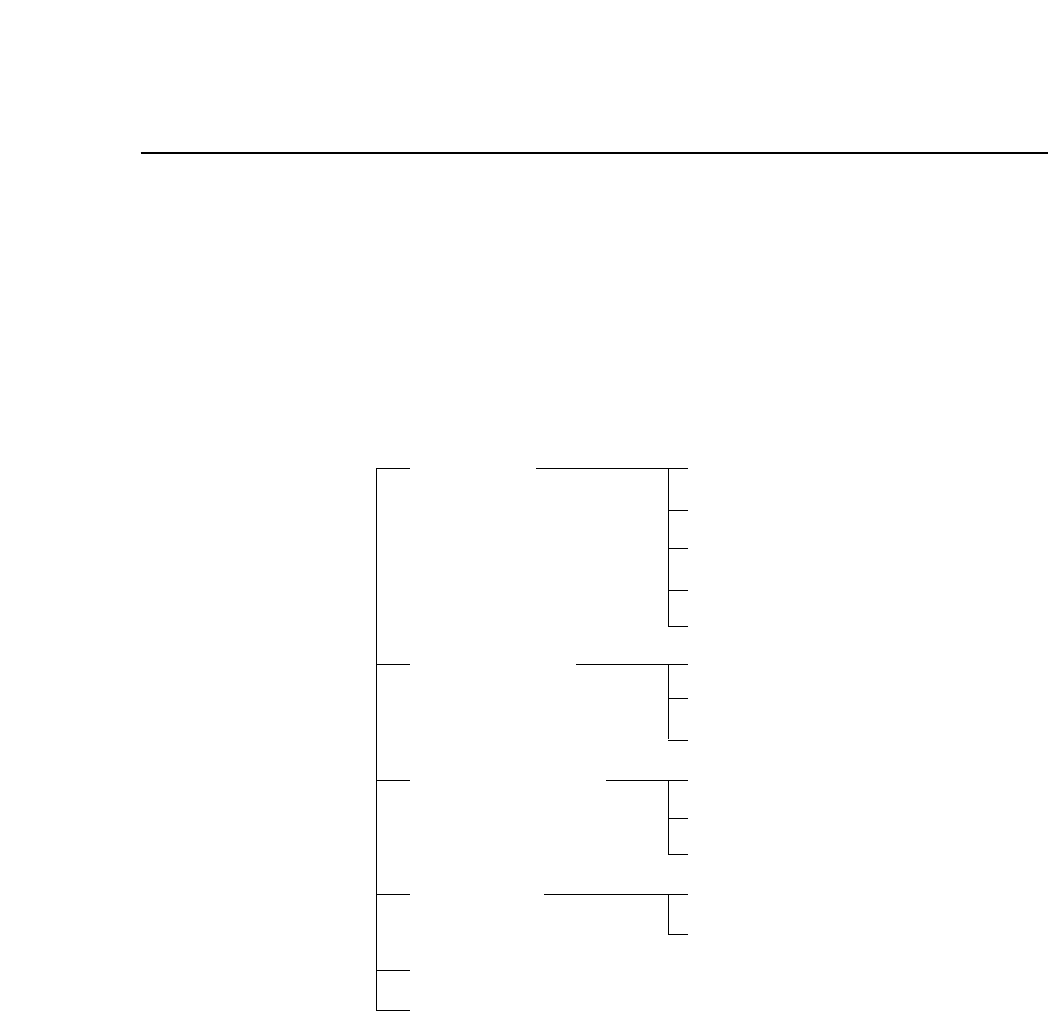
4.1 Categories of Parts
The parts of the machine may be grouped in the following categories for
convenience.
Placing Cam Box
Rotary Turret
Placing Head
Stations 1 to 12
Vision Processing
Parts Supply Feeders
CP IV-3 Device Table
Tape Cutter
Board Transport XY Table
In conveyor
Out conveyor
Electrical Operation Panel
Control Box
Air Supply
Machine Body
Version 1.0 4 – 1

4 – 2Version 1.0
Chapter 4 Functions of the Parts
4.2 Placing System
• Cam Box
The cam box, which is located in the upper part of the machine,
consists of the cam axis motor, cams, cam axes, cam levers, rotary
solenoids and related items. Each cam initiates the indexing
movement of the rotary turret which drives the placing heads from
stations 1 to 12.
• Rotary Turret
The rotary turret, which is located between the cam box and the
placing head, consists of the housing, spindle, holder and related
items. This turret indexes the movements of the 12 placing heads.
• Placing Head
The 12 placing heads, which are attached around the sides of the
rotary turret, each consist of the nozzles, holder, shaft and related
items. The placing head carries 3 sizes (S, M and L) of nozzles, the
usages of which are determined by the size of the part to be picked.
The head picks parts from the feeder, holds them for vision
processing, and places parts on the board during production.
• Stations 1 to 12
The 12 placing head positions are each assigned a station number.
Each of these stations has a special function, as explained below.
Station 1 : The head picks parts from the feeder, advances the
feeder tape and checks for the tape end.
Station 2 : A sensor checks for the presence of large parts.
Station 3 : The machine performs pre-theta (Pθ) adjustment. Pre-
theta rotates the part 0°, +90° or -90° depending on the
value that is set in the program. After vision processing
is carried out at station 4, fine theta (Fθ) rotation can be
carried out at station 6. Because the rotation done in
fine theta is usually very small, the part will not slip as
much, and placement speed is therefore faster than on
previous models.
Station 4 : Either the wide or narrow range CCD camera checks
whether or not the part was picked, that the part is
centered on the nozzle, and that the part shape is
correct.
Station 5 : No function.

Chapter 4 Functions of the Parts
Station 6 :Fine theta (Fθ) adjustment is carried out. The results of
vision processing are sent to the the servomotor, and
final adjustments are made to the angle of the part.
Station 7 :The machine places the part on the board. If the vision
processing declares that the part is no good (NG), the
part is not placed.
Station 8 : No function.
Station 9 :A sensor checks whether or not the nozzle has returned
to the original position after placement. A check of the
position of nozzle holder A is also done in order to
process production information.
Station 10 : Parts declared defective by vision processing are
rejected here. Also, because of upcoming nozzle
changeover at station 11, the locations of the S, M and L
nozzles are confirmed.
Station 11 : S, M and L nozzles are changed.
Station 12 :After nozzles are changed, their locations are checked at
this station. The nozzle vacuum turns off as the spool is
pushed in.
• Vision Processing
In addition to the part recognition described at station 4, the vision
processing system includes a CCD camera, light, CCD camera
mounting bracket and related parts.
The camera reads the fiducial marks on the board to enable
corrections to be made in the position of the board. This CCD camera
unit is the optical correction unit.
Version 1.0 4 – 3