CP43维护手册.pdf.pdf - 第55页
5 – 13 V ersion 6.0 Chapter 5 The T welve Stations 5.1.5 Cutting W aste T ape After parts have been picked out of the tape, the empty “waste” tape is cut off. W aste tape that has been cut is collected by a vacuum at the…
Chapter 5 The Twelve Stations
• Sensitivity Adjustment
1) Set an 8W x 4P paper tape feeder on the device table and move
it to station 1.
2) Press the EMERGENCY STOP button to take the machine from
200 volts down to 100 volts.
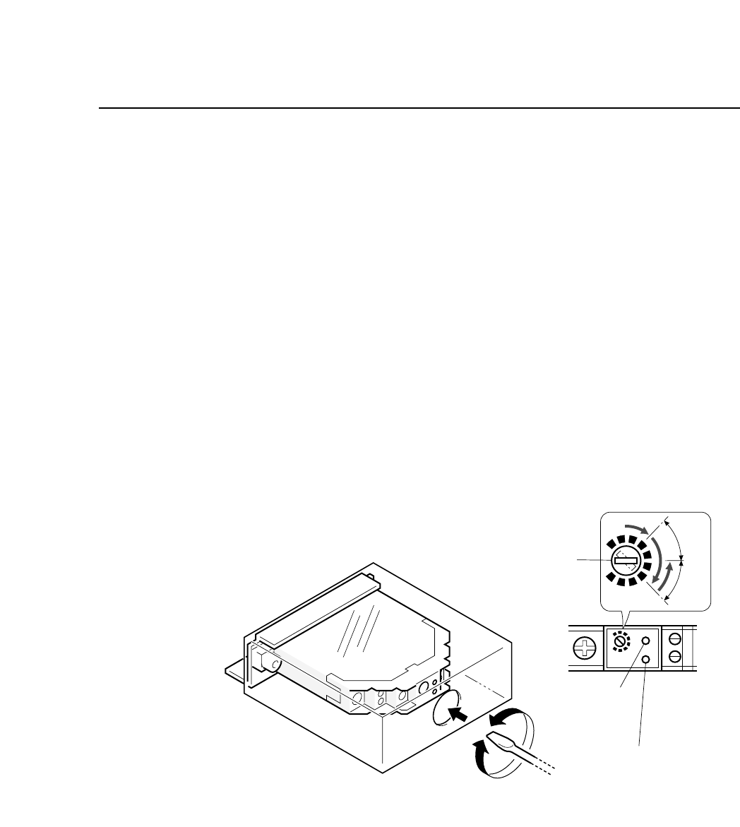
3) Turn the sensitivity trimmer volume to zero. Slowly turn the
trimmer to the right to a position where green LED goes on
(position A).
4) Remove the paper tape from the feeder. The green LED will go
off.
5) Adjust the trimmer volume to the right to the position where
the green LED goes on (position B).
6) Set the trimmer volume between position A and position B.
7) Ensure that the sensor actually detects the end of the tape.
Fig. 5-12 Station 1 Tape End Sensor Volume Adjustment
Sensitivity adjustment
trimmer
Green LED
Red LED
SET
A
B
"
"
5 – 12
Version 6.0
CP IV-3 Maintenance
5 – 13
Version 6.0
Chapter 5 The Twelve Stations
5.1.5 Cutting Waste Tape
After parts have been picked out of the tape, the empty “waste”
tape is cut off. Waste tape that has been cut is collected by a
vacuum at the back of the machine.
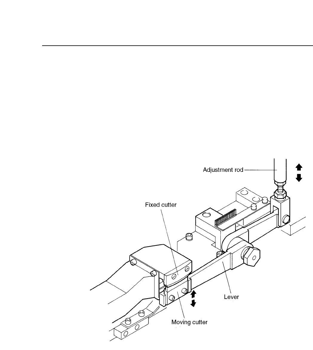
The waste tape cutting operation is driven by a cam mechanism.
The cam drives a lever, which drives a rod, which drives a lever,
which drives the cutter.
The stroke of the rod is a fixed value determined by the curve of the
cam.
Fig. 5-13 Waste Tape Cutting Mechanism
CP IV-3 Maintenance
Chapter 5 The Twelve Stations
Follow the procedure below to adjust the stroke of the waste tape
cutter claw.
(1) Attach the cam handle on the handle shaft. Turn the handle
until the cam angle indicator reads 245°.
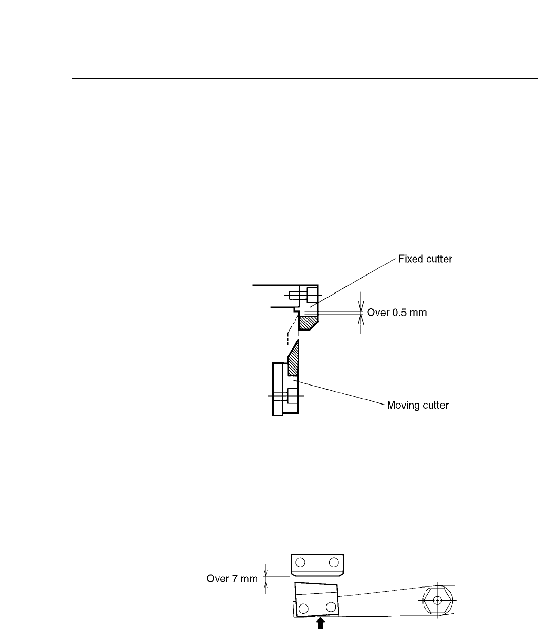
(2) With the cam angle set to 245°, adjust the rod so that the
moving cutter touches the fixed cutter. At this time, the gap
between the the tip of the moving cutter and the underside of
the fixed cutter should be more than 0.5 mm.
Fig. 5-14 Gap Between Moving and Fixed Cutter
(Cam Angle 245°)
(3) Return the cam angle to 0°. Confirm that the gap between the
moving cutter and the fixed cutter is more than 7 mm, and that
the moving cutter lever does not contact the plate.
Fig. 5-15 Gap Between Moving and Fixed Cutter
(Cam Angle 0°)
5 – 14
Version 6.0
CP IV-3 Maintenance