CP43维护手册.pdf.pdf - 第60页
Chapter 5 The T welve Stations 5.1.8 T urning the Nozzle V acuum V alve ON By activating the valve switch at station 1, the vacuum within the nozzle switches from of f to on (the spool is pulled out). When the valve is t…
5 – 17
Version 6.0
Chapter 5 The Twelve Stations
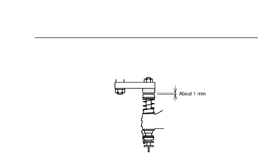
(7) Return the cam angle to 0°. Confirm that the gap between the
pusher and the top of the nozzle is about 1 mm.
Fig. 5-18 Gap Between Nozzle and Pusher (Cam Angle 0°)
CP IV-3 Maintenance
Chapter 5 The Twelve Stations
5.1.8 Turning the Nozzle Vacuum Valve ON
By activating the valve switch at station 1, the vacuum within the
nozzle switches from off to on (the spool is pulled out).
When the valve is turned on the inside of the nozzle becomes a
vacuum which enables the nozzle to pick up a part.
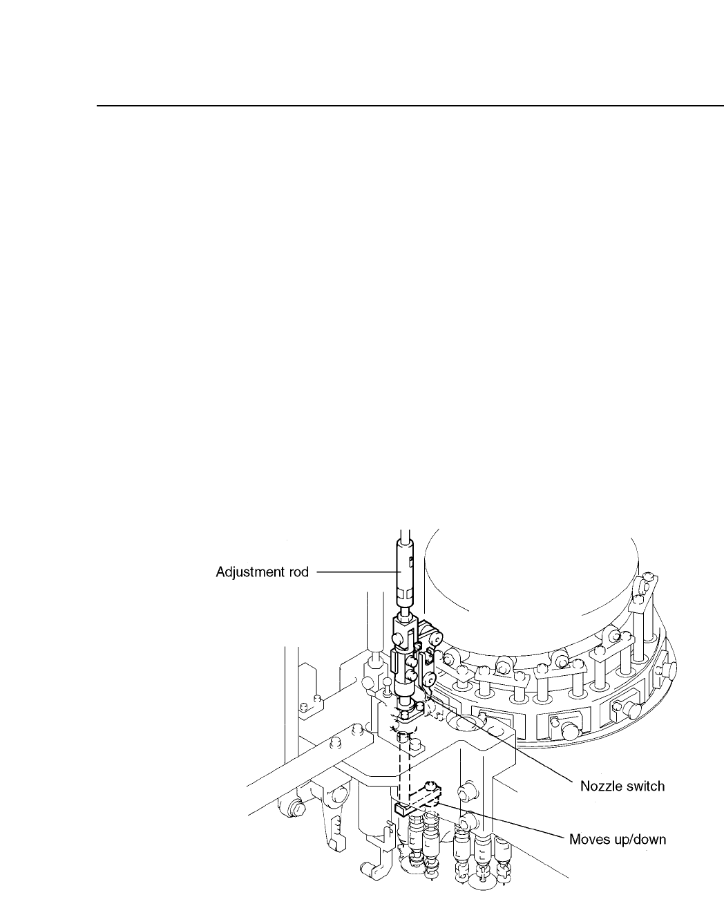
The adjustment rod, besides triggering the valve switch, also drives
the nozzle upward and downward stroke (see illustration below).
Thus after adjusting the nozzle upward and downward stroke or
the valve switch, confirm that the adjustment made to one of these
two settings has not affected the other setting. If this confirmation
is neglected, machine damage may result.
The valve activation operation is driven by a cam mechanism. The
cam drives a lever, which drives a rod, which drives a lever, which
drives the spool.
The stroke of the rod is a fixed value determined by the curve of the
cam.
Fig.5-19 Valve Switching Mechanism at Station 1
5 – 18
Version 6.0
CP IV-3 Maintenance
5 – 19
Version 6.0
Chapter 5 The Twelve Stations
Follow the procedure below to adjust the ON/OFF operation of the
nozzle valve.
(1) Press [SET], [MANUAL], [I/O] and [EMERGENCY STOP] to
cut the 200V but still leaving the 100V power supply on.
(2) Enter the I/O map and press [OUT], [+Page]; then use the ▼ or
▲ key to move the cursor to the item titled “Y020 PICKUP SOL
ON”. Using the [ON/OFF] button, change the displayed “X”
to “O”. This operation turns off station 1’s solenoid stopper. If
the solenoid is not turned off, adjustment is impossible.
(3) Attach the cam handle to the cam shaft. Turn the handle until
the cam angle indicator reads 230°.
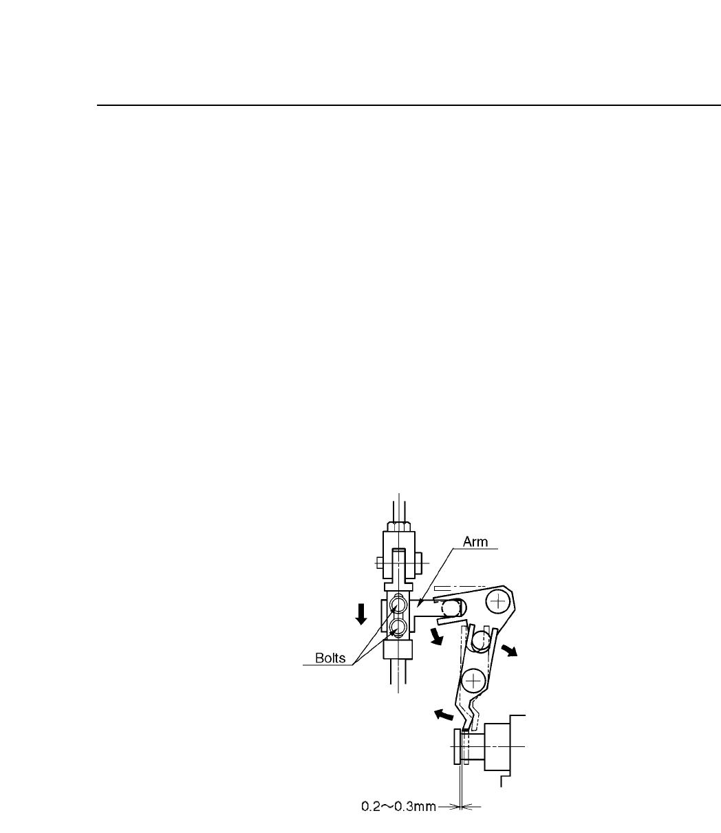
(4) With the cam angle at 230° and the spool pulled all the way
out, loosen the two bolts and adjust the vertical position of the
arm so that there is 0.2~0.3 mm between the spool flange and
the valve ON/OFF lever.
Fig. 5-20 Spool Flange and Valve ON/OFF Lever Gap
(Cam Angle 230°)
CP IV-3 Maintenance