CP43维护手册.pdf.pdf - 第69页
5 – 27 V ersion 6.0 Chapter 5 The T welve Stations 5.5 Station 5 Station 5 has no function. CP IV -3 Maintenance
Chapter 5 The Twelve Stations
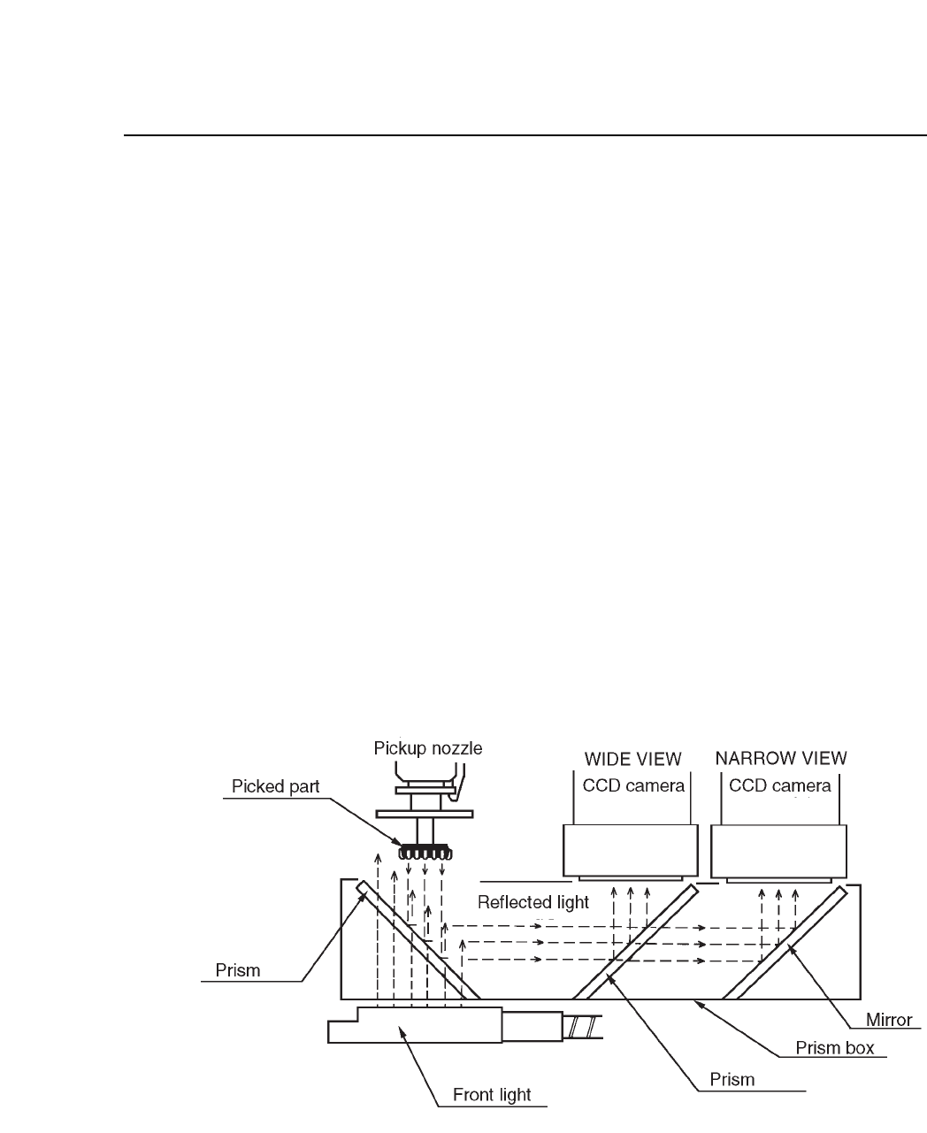
Front Lighting Specifications
To use the front light, Part data item 13.Lighting must be set to
Front_ligt. Proper data item 126. Frontlight must also be set to Use.
1. The halogen light shines from the front light onto the prism.
2. The halogen light passes through the prism then simultaneously
reflects onto the part leads and returns to the prism.
3. The part image reflected off the prism is reflected at and permeated
through another prism.
4. The reflected image goes to the wide view CCD camera, and the
permeated, to the narrow view CCD camera. The CCD camera which
is used is specified in the MCS/2 Part data file.
5. Either the wide or narrow view camera sends information and
compares it with what is in Part data, and the machine decides
whether or not to place the part. If the part is to be placed,
information on X, Y and theta coordinates is sent out to correct pickup
deviation. The XY table adjusts itself and fine-theta is carried out at
station 6.
Fig. 5-27 Light Reflection During Front Light Vision Processing
5 – 26
Version 6.0
CP IV-3 Maintenance

5 – 27
Version 6.0
Chapter 5 The Twelve Stations
5.5 Station 5
Station 5 has no function.
CP IV-3 Maintenance
Chapter 5 The Twelve Stations
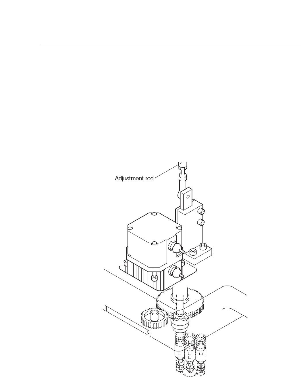
5.6 Station 6
At station 6, fine theta axis adjustment is done. Using the vision
processing data from station 4, station 6 rotates the part to its final placing
angle.
The fine theta axis adjustment combines vertical and rotational
movement.
The fine theta axis adjustment operation is driven by the rotation of a
motor and a cam mechanism. The cam drives a lever, which drives a rod,
which drives a rod, which drives the clutch.
Fig. 5-28 Fine Theta (F
θ
) Mechanism at Station 6
5 – 28
Version 6.0
CP IV-3 Maintenance