CP43维护手册.pdf.pdf - 第76页
Chapter 5 The T welve Stations (2) Enter the I/O map and press [OUT], [+Page], then use the ▼ or ▲ key to move the cursor to the item titled “Y028 PLACE SOL ON”. Using the [ON/OFF] button change the displayed “X” to “O”.…
5 – 33
Version 6.0
Chapter 5 The Twelve Stations
5.7 Station 7
At station 7, in order to carry out part placement, the nozzle moves up
and down and the valve turns on and off.
5.7.1 Nozzle Up/down Stroke
The nozzle places the part on the board.
The nozzle upward and downward operation is driven by a cam
mechanism. The cam drives a lever, which drives a rod, which
drives a lever, which drives the nozzle.
The stroke of the rod is a fixed value determined by the curve of the
cam.
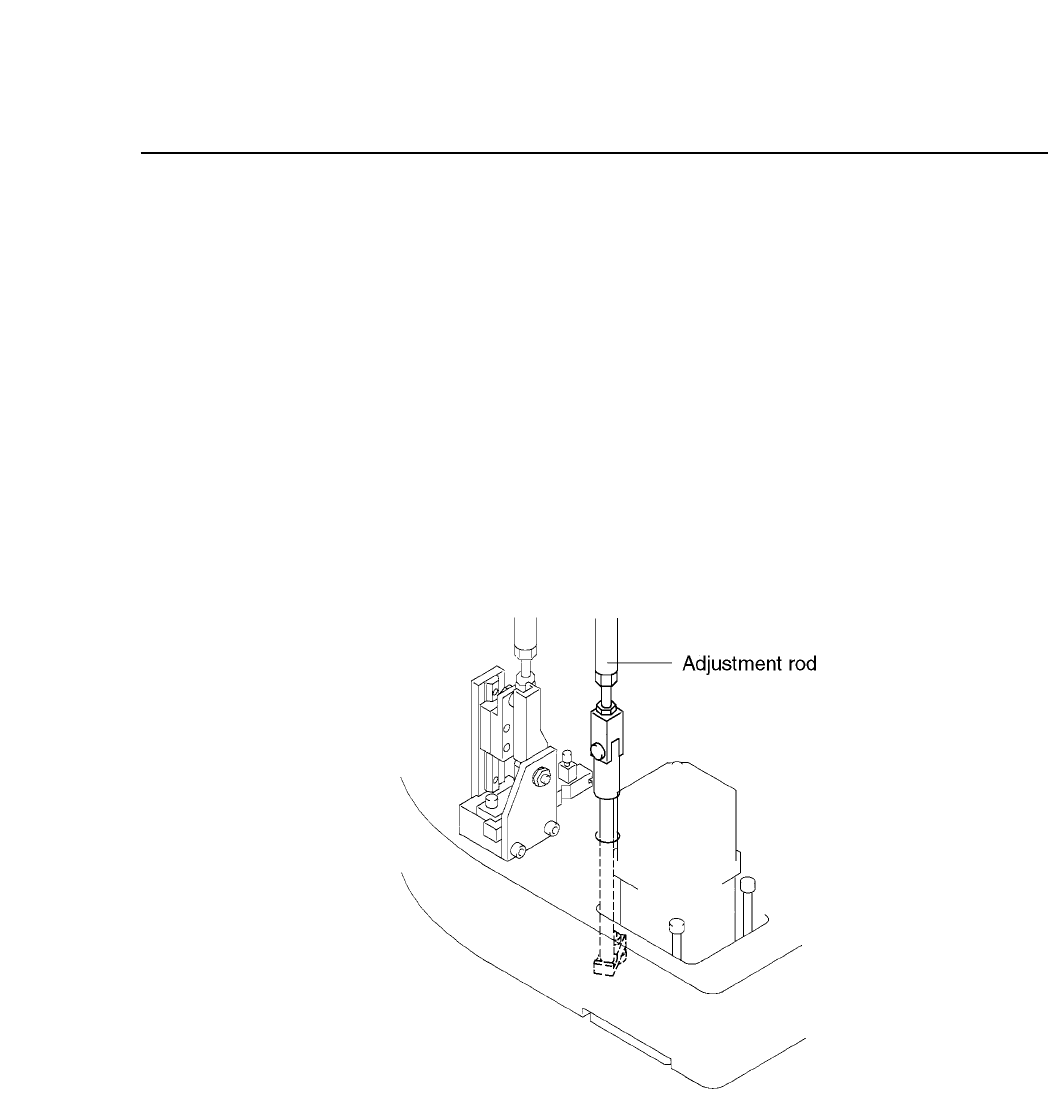
Fig. 5-34 Nozzle Vertical Operation Mechanism at Station 7
Follow the procedure below to adjust the nozzle upward and
downward stroke.
(1) Press [SET], [MANUAL], [I/O] and [EMERGENCY STOP] to
cut the 200V power but leaving the 100V power supply on.
CP IV-3 Maintenance
Chapter 5 The Twelve Stations
(2) Enter the I/O map and press [OUT], [+Page], then use the ▼ or
▲ key to move the cursor to the item titled “Y028 PLACE SOL
ON”. Using the [ON/OFF] button change the displayed “X” to
“O”. This operation turns off station 7’s solenoid stopper. If
the solenoid is not turned off, adjustment is impossible.
(3) Attach the cam handle to the cam shaft. Turn the handle until
the cam angle indicator reads 175°.
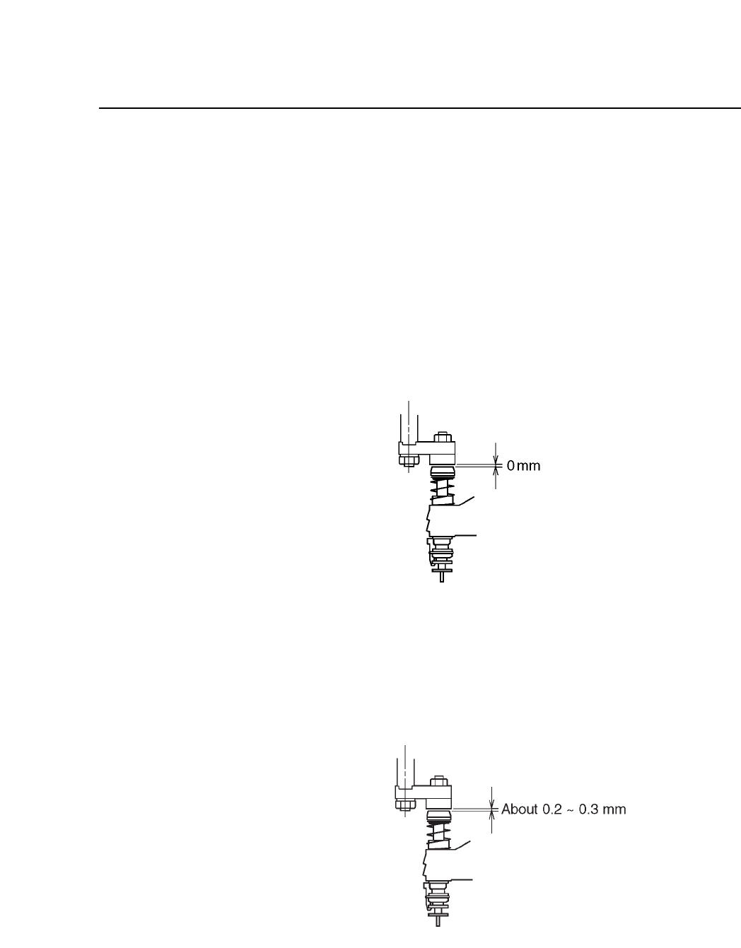
(4) With the cam angle at 175°, adjust the adjusting rod so that
there is no space between the upper surface of the nozzle clutch
and the pusher.
Fig. 5-35 Nozzle Clutch and Pusher Gap
(Cam Angle 175°)
(5) Return the cam angle to 0°. Confirm that the gap between the
upper surface of the nozzle clutch and the pusher is 0.2 ~ 0.3
mm.
Fig. 5-36 Nozzle Clutch and Pusher Gap
(Cam Angle 0°)
5 – 34
Version 6.0
CP IV-3 Maintenance
5 – 35
Version 6.0
Chapter 5 The Twelve Stations
5.7.2 Turning the Valve ON/OFF
By activating the valve at station 7, the vacuum within the nozzle
switches from off to on (the spool is pushed) and at the same time
the air that turns on the vacuum generator is supplied. By turning
the valve off, the vacuum within the nozzle is destroyed and part
placement is made possible.
When the valve is turned on the inside of the nozzle becomes a
vacuum which enables the nozzle to pick up a part.
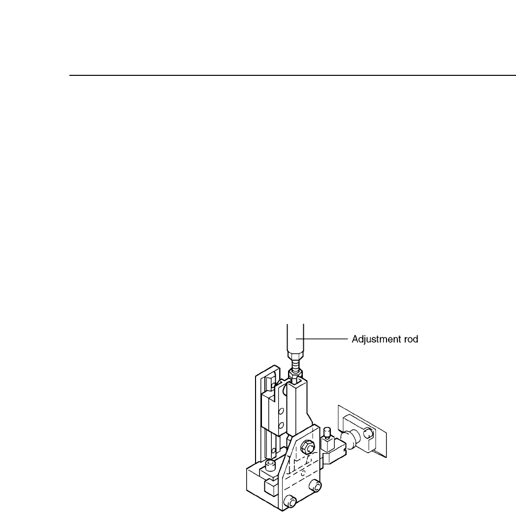
The operation of turning the valve on and off is driven by a cam
mechanism. The cam drives a lever, which drives a rod, which
drives a lever, which drives the slide.
The stroke of the rod is a fixed value determined by the curve of the
cam.
Fig. 5-37 Valve Activation Operation Mechanism at Station 7
Follow the procedure below to adjust the activation and
deactivation of the nozzle valve.
(1) Press [SET], [MANUAL], [I/O] and [EMERGENCY STOP] to
cut the 200V power supply but still leaving the 100V power
supply on.
(2) Enter the I/O map and press [OUT], [+Page] then use the [▼]
or [▲] key to move the cursor to the item titled “Y028 PLACE
SOL ON”.
(3) Make sure the spool is pushed in.
CP IV-3 Maintenance