CP43维护手册.pdf.pdf - 第81页
5 – 39 V ersion 6.0 Chapter 5 The T welve Stations 5.9.2 Holder A Check The holder A check consists of simply noting the position of nozzle holder A. The nozzle holder A position data is used as production information. A…
Chapter 5 The Twelve Stations
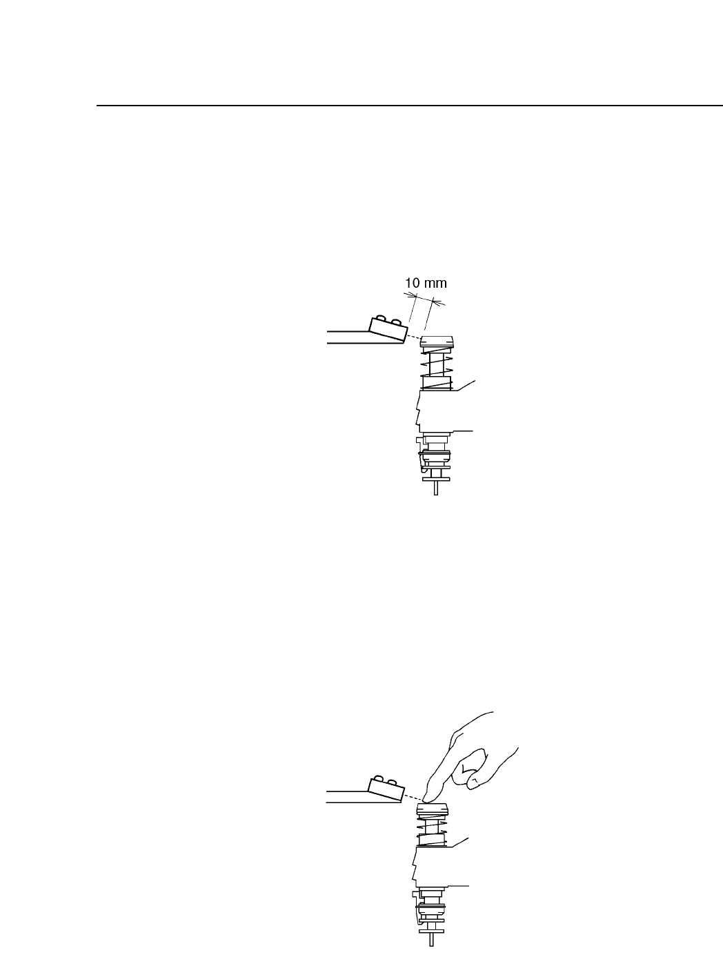
Follow the procedure below to adjust the stroke of the nozzle.
(1) With the cam angle set to 0°, adjust the securing bracket so that
the sensor will touch the nozzle clutch’s tapered surface. The
distance between the sensor and the nozzle clutch’s tapered
surface is 10 mm.
Fig. 5-41 Sensor and the Nozzle Clutch at Station 9
(2) Set the amplifier volume to MAX. The amplifier is on the left
side of station 9 (as seen from the front).
(3) Attach the cam handle on the cam shaft, and turn the handle
until the cam indicator reads 235°.
(4) With the cam angle set at 235°, push the nozzle down 1 to 1.5
mm and confirm that the pilot lamp goes off.
Fig. 5-42 Pushing Nozzle Down
5 – 38
Version 6.0
CP IV-3 Maintenance
5 – 39
Version 6.0
Chapter 5 The Twelve Stations
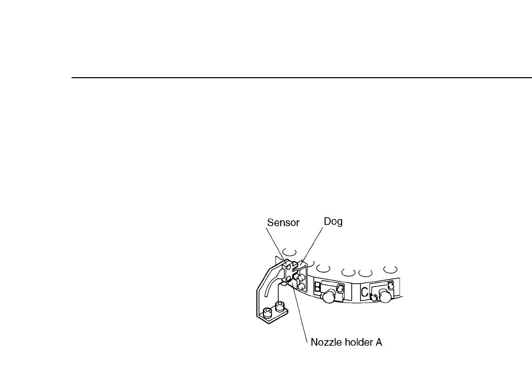
5.9.2 Holder A Check
The holder A check consists of simply noting the position of nozzle
holder A. The nozzle holder A position data is used as production
information.
Adjustment is unnecessary.
Fig. 5-43 Holder A Check at Station 9
CP IV-3 Maintenance
Chapter 5 The Twelve Stations
5.10Station 10
At station 10, parts determined to be rejects during vision processing are
thrown away. In addition, the nozzle pre-changeover check is carried out
in anticipation of the nozzle switch at station 11.
5.10.1Throwing Away Reject Parts
At Station 10, if the part was determined to be NG (no good) as a
result of vision processing at Station 4, then the rejects parts
disposal mechanism pushes down the spool cutting the air supply
to the vacuum, so the part releases from the nozzle and falls into
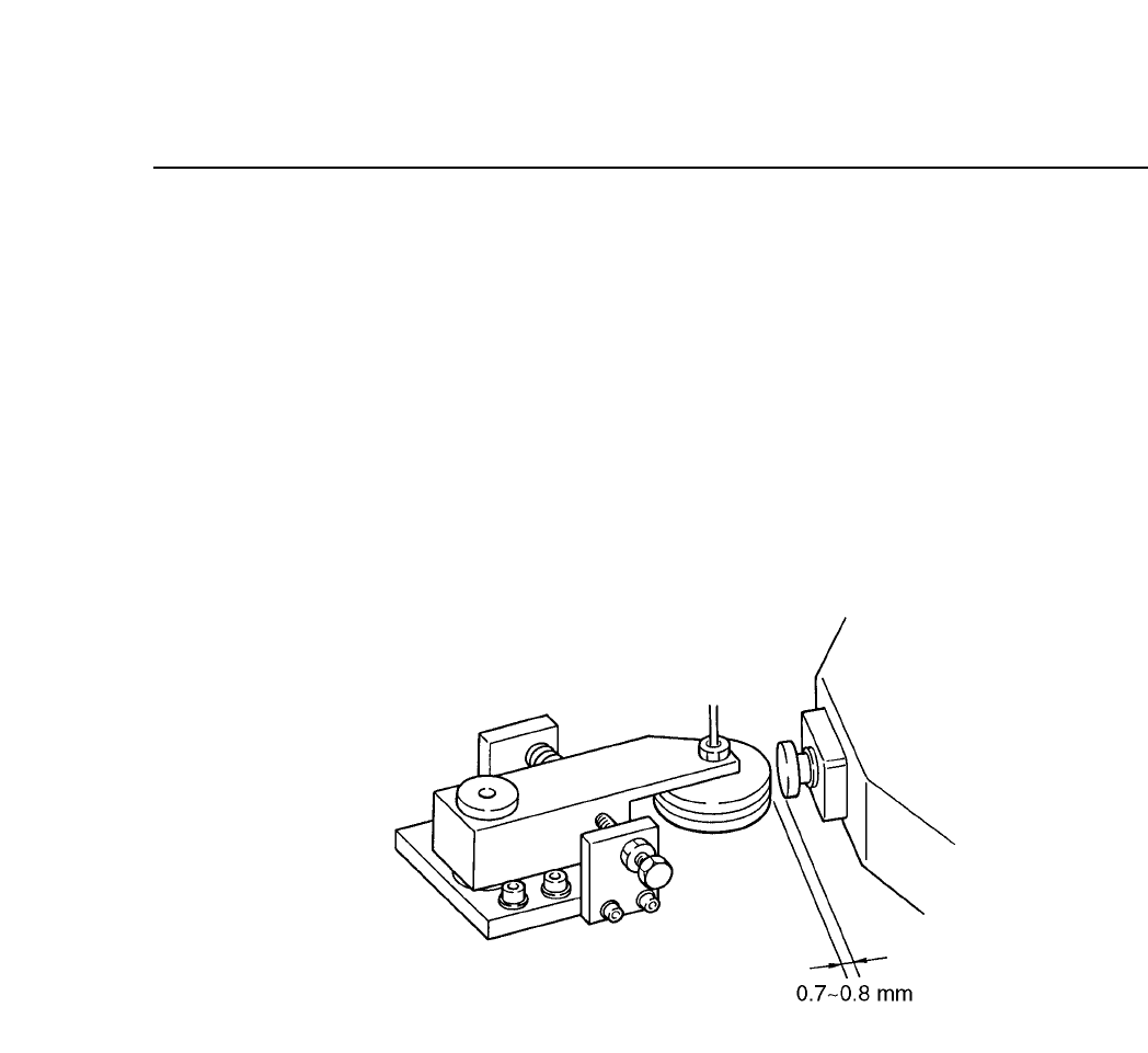
Fig. 5-44 Reject Parts Disposal Mechanism
Follow the procedure below to adjust the activation operation of
the reject parts disposal mechanism.
(1) With the cam angle set to 330° and the spool pushed in, adjust
the set bolts on the side of the roller so that there is 0.7 to 0.8
mm between the roller and the spool.
(2) Turn the roller so that the hole from which the air is expelled
matches the hole on the spool from which the air is drawn in.
(3) After the adjustment, check that the pooled out spool returns to
the pulled out position, manually using the roller. For the air
release valve, tighten the knob completely, and then loosen 3.0
rotations.
5 – 40
Version 6.0
CP IV-3 Maintenance