CP43维护手册.pdf.pdf - 第94页
Chapter 7 The Device T ables Fig. 7-1 Slider Structure and Principal Parts 7 – 2 V ersion 7.0 CP IV -3 Maintenance

Chapter 7 The Device Tables
7. The Device Tables
The term “device” refers to the location of a tape feeder.
The tape feeders are set up on the device table in the arrangement the program
specifies. During production the D-axis tables move the tape feeders directly
under station 1 in the order specified by the program. Afterwards, the nozzle
from station 1 lowers and picks up the part.
The two D-axis tables can operate in the following three modes:
• Device change mode
When the parts run out on one table, the other table is automatically
selected.
• Changeover mode
Only one table operates at a time. The other table is automatically selected
at the end of the current production program.
• Joint mode
The two tables with 80 devices each are joined to make one table with 160
devices.
For the CP IV and CP IV-2, the two device tables are linked by a mechanism
called the slider.
The device tables on the CP IV-3 each have their own motor and can work
independently of the other. In the joint mode, the two device tables are used
together during production.
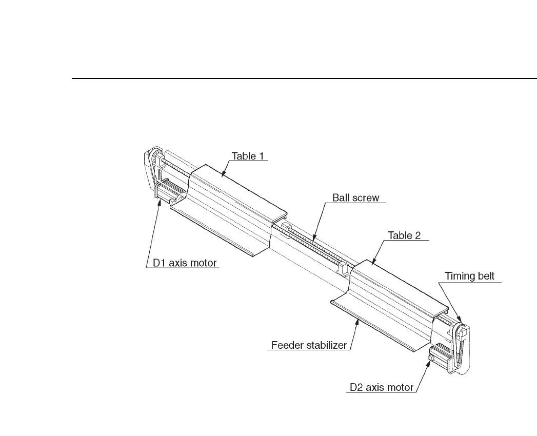
7.1 Device Table Configuration
The slider and its principal parts are shown on the following page.
7 – 1Version 7.0
CP IV-3 Maintenance
Chapter 7 The Device Tables
Fig. 7-1 Slider Structure and Principal Parts
7 – 2Version 7.0
CP IV-3 Maintenance
Chapter 7 The Device Tables
7.2 Preventing Device Table Collisions
Since the two device tables can work independently, an interlock is used
to prevent collisions when they are working in close proximity to each
other.
Two types of interlocks are used, one is in the software and the other is a
sensor on the machine.
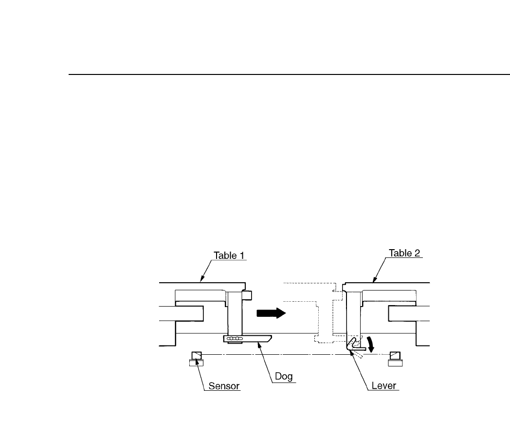
The sensor is depicted in the following figure.
Fig. 7-2 Device Table Interlock Sensor
When the tables are approaching each other, a dog presses down on a
lever. This lever trips the sensor and causes the machine to stop.
7 – 3Version 7.0
CP IV-3 Maintenance