00197463-03_SM_CPP_Customer_EN.pdf - 第29页
4 Component camera and component sensor 4.1 Replacing the component camera [03018637‑xx] Service Manual SIPLACE Multistar (CPP / CPP M) 02/2018 29 4 Component camera and component sensor 4.1 Replacing the component camer…
3 Usability package
3.2 Retrofitting the usability package
28 Service Manual SIPLACE Multistar (CPP / CPP M) 02/2018
Assembly of:
●
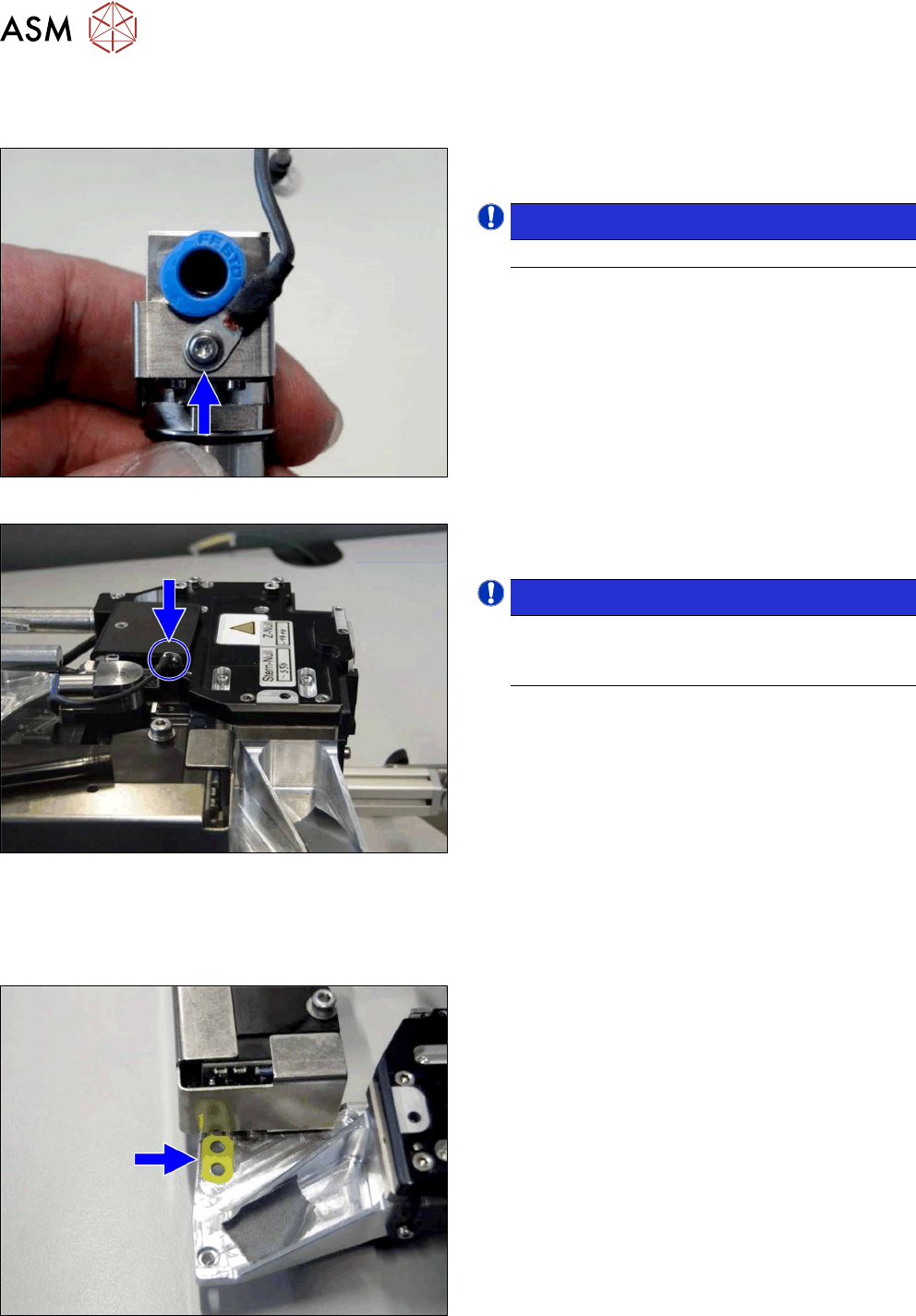
Ground connection (ground slit) of screwed joint CPP [03120256‑xx]
Fig.25: Fastening the ground connection to the screwed joint
► Screw the new ground connection to the screwed
joint using the straight cable lug.
NOTICE!
Observe the correct installation direction.
.
Fig.26: Fastening the ground connection to the front section of
the head
► Fit the ground connection to the front section of
the head using the curved cable lug (if present).
NOTICE!
Make sure that the curved cable lug does not
protrude beyond the handle protector for the
CPP.
.
Assembly of:
●
Label assembly marking CPP [03118678‑xx]
Fig.27: Fitting the label
► Attach the label to the position shown.
4 Component camera and component sensor
4.1 Replacing the component camera [03018637‑xx]
Service Manual SIPLACE Multistar (CPP / CPP M) 02/2018 29
4 Component camera and component sensor
4.1 Replacing the component camera [03018637‑xx]
Parts, equipment and tools
●
Select the required spare part:
– Component camera C&P (type 23) 6x6 GigE [03105195Sxx]
– Component camera C&P (type 29) 27x27 digital RK [03018637Sxx] (without GigE)
– Component camera C&P (type 30) 27x27 GigE [03101672Sxx]
– Component camera C&P (type 38) 16x16 digital RK [03051870Sxx]
– Component camera CPP (type 45) 15x15 GigE [03106380Sxx]
Overview
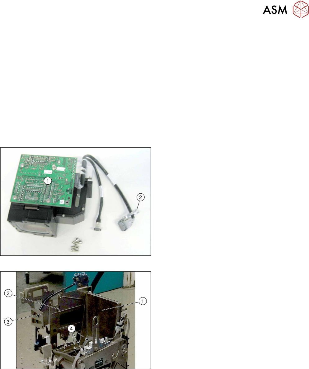
Fig.28: Component camera
1. Illumination control
2. Cable holder
Fig.29: CPP head without component camera
1. Mounting position for the component camera
2. Fixing hole on the board holder
3. Fixing hole on the bracket
4. Fixing holes for the foot of the component cam-
era (two each on each side)
4 Component camera and component sensor
4.1 Replacing the component camera [03018637‑xx]
30 Service Manual SIPLACE Multistar (CPP / CPP M) 02/2018
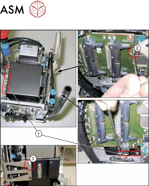
Fig.30: Fixture points for component camera
1. Screws at the foot of the camera 4x)
DIN912-M3x16-A2-70 [00325349-xx]
2. Screw on the board holder (1x)
ISO4762-M2.5x4-A2-70 [03042531-xx]
DIN125-A2.7-140HV-A2 [00201583-xx]
3. Screw on the retaining bracket (1x)
ISO 4762 - M 2.5 x 4-A2-70 [03042531-xx ]
DIN 125-A 2.7-140HV-A2 [00201583-xx]
Preparation
► Remove the head from the machine. For details about removing and fitting the placement
head, refer to the service manual for your machine.
fit the head on the head mount [03056231‑xx].
► Make sure that the component sensor protective cap is fitted.
1.1.3 "Protecting the component sensor" [}8]
Removal
► Open the cable holders for the component camera cable.
► Remove the six screws fastening the component camera.
(4x on the camera base, 1x on the board holder, 1x on the retaining bracket)
► Carefully pull the component camera off the locating pins.