00197463-03_SM_CPP_Customer_EN.pdf - 第109页
9 Intermediate distributor and vacuum sensor 9.2 Replacing Intermediate Distributors 1 and 2 Service Manual SIPLACE Multistar (CPP / CPP M) 02/2018 109 Installation ► Follow the removal instructions in reverse order for …
9 Intermediate distributor and vacuum sensor
9.2 Replacing Intermediate Distributors 1 and 2
108 Service Manual SIPLACE Multistar (CPP / CPP M) 02/2018
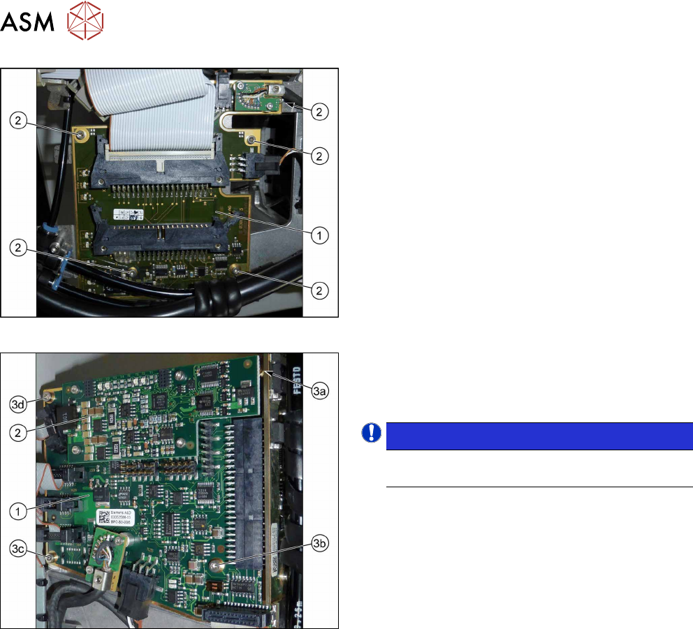
Fig.182: Intermediate distributor 1
1. Intermediate distributor 1 (ID1)
2. Five fastening screws
Fig.183: Intermediate distributor 2
1. Intermediate distributor 2 (ID2)
2. KE control board ID2
3. Four fixing screws
NOTICE!
To remove the screw (3a), first dismantle and re-
move the KE control board for ID2 (2).
.
Preparation
► Remove the head from the machine. For details about removing and fitting the placement
head, refer to the service manual for your machine.
fit the head on the head mount [03056231‑xx].
► Make sure that the component sensor protective cap is fitted.
1.1.3 "Protecting the component sensor" [}8]
Removal
► For ID2 only: Dismantle and remove the KE control board ID2.
9.1 "Replacing the KE Control Board ZV2 [03073355-xx]" [}105]
► Disconnect all connectors from the board. You may want to mark their positions, to make
clear assignment easier later on.
► Remove the screws fastening the board (ID1:5x, ID2:4x).
► Carefully lift off the board. Take care not to damage the press-fit connection to the other ID.
9 Intermediate distributor and vacuum sensor
9.2 Replacing Intermediate Distributors 1 and 2
Service Manual SIPLACE Multistar (CPP / CPP M) 02/2018 109
Installation
► Follow the removal instructions in reverse order for further installation.
Also observe the installation instructions in the following section:
9.1 "Replacing the KE Control Board ZV2 [03073355-xx]" [}105]
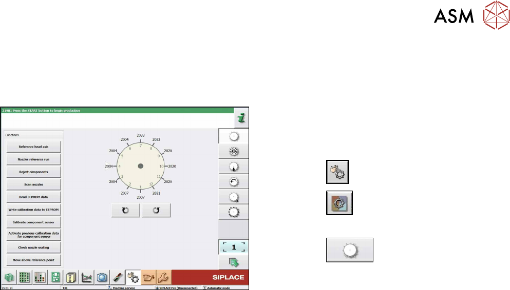
Fig.184: Checking the status and function of the heads
Only when replacing ID1:
After the machine has been restarted write the cali-
bration values from the machine data to the head EE-
PROM. To do so, proceed as follows:
► Click the
button.
► Click the
button.
► Select the head.
► Click the
button.
► Click on the button Write calibration data to EE-
PROM.
9 Intermediate distributor and vacuum sensor
9.2 Replacing Intermediate Distributors 1 and 2
110 Service Manual SIPLACE Multistar (CPP / CPP M) 02/2018
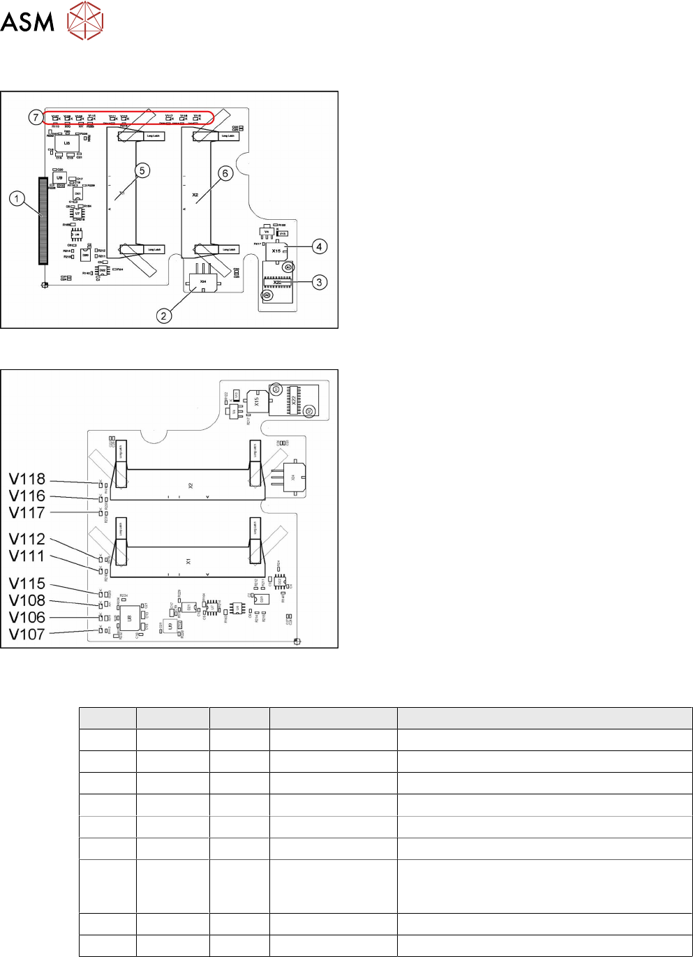
9.2.1 Intermediate distributor ZV1/CPP [03065295-xx]
03065295-02
The intermediate distributor 1 (ID1) establishes the
connection to the intermediate distributor 2 (ID2) and
the adapter board. In addition, various sensors and
actuators for the CPP head are directly connected
here.
1. X25 – connector to ID2
2. X24 – Z motor
3. X22 – connector Z axis encoder (track signals)
with EEPROM
4. X15 – return cylinder
5. X1 – flat ribbon cable connector to head adapter
6. X2 – flat ribbon cable connector to the head ad-
apter
7. LEDs V107 to V118 (see below)
03065295-02
LED overview
LED [03065295-02]
LED Color Status Signal name Description
V106 GN ON 15V+ +15VDC operating voltage
V107 GN ON 5V+ +5VDC operating voltage
V108 GN ON 15V- -15VDC operating voltage
V111 RD ON Z_COUNT_ERR Z axis sensor error
V112 RD ON S_COUNT_ERR Star axis sensor error
V115 GN ON 3.3V+_DP +3.3VDC DP operating voltage
V116 YE ON STATUS_PRES-
SURECONTROL-
VALVE
Status: control valve pressure OK
V117 YE ON Z_BOTTOM_LED Z_bottom sensor ON
V118 YE ON V4_OUT Return cylinder extended