00197463-03_SM_CPP_Customer_EN.pdf - 第111页
9 Intermediate distributor and vacuum sensor 9.2 Replacing Intermediate Distributors 1 and 2 Service Manual SIPLACE Multistar (CPP / CPP M) 02/2018 111 9.2.2 Intermediate distributor ZV2/CPP [03052586-xx] 03052586-03 Int…
9 Intermediate distributor and vacuum sensor
9.2 Replacing Intermediate Distributors 1 and 2
110 Service Manual SIPLACE Multistar (CPP / CPP M) 02/2018
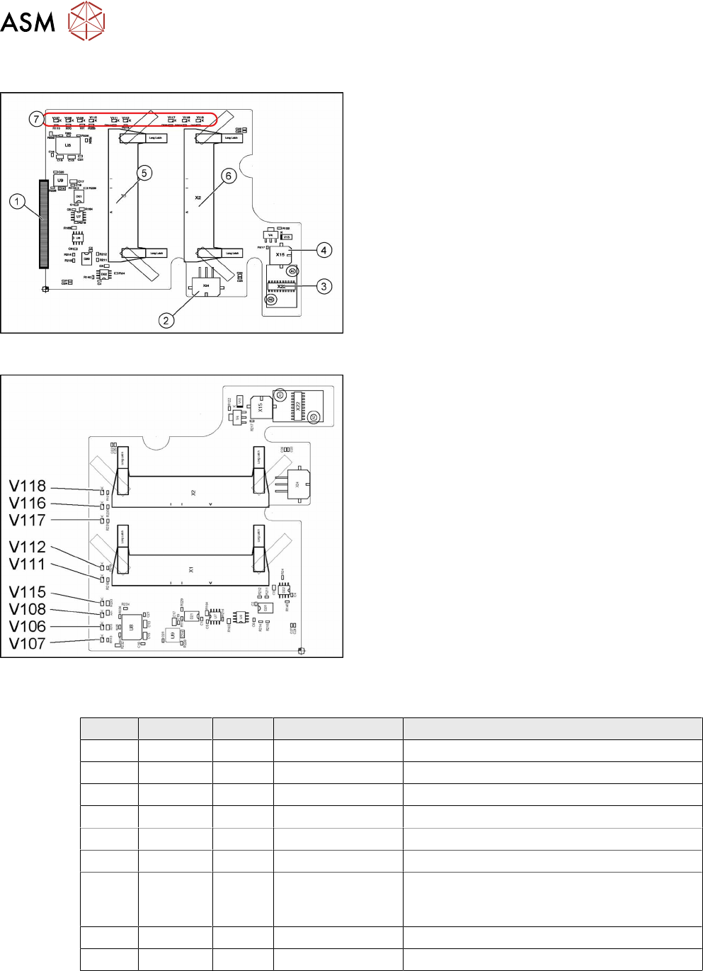
9.2.1 Intermediate distributor ZV1/CPP [03065295-xx]
03065295-02
The intermediate distributor 1 (ID1) establishes the
connection to the intermediate distributor 2 (ID2) and
the adapter board. In addition, various sensors and
actuators for the CPP head are directly connected
here.
1. X25 – connector to ID2
2. X24 – Z motor
3. X22 – connector Z axis encoder (track signals)
with EEPROM
4. X15 – return cylinder
5. X1 – flat ribbon cable connector to head adapter
6. X2 – flat ribbon cable connector to the head ad-
apter
7. LEDs V107 to V118 (see below)
03065295-02
LED overview
LED [03065295-02]
LED Color Status Signal name Description
V106 GN ON 15V+ +15VDC operating voltage
V107 GN ON 5V+ +5VDC operating voltage
V108 GN ON 15V- -15VDC operating voltage
V111 RD ON Z_COUNT_ERR Z axis sensor error
V112 RD ON S_COUNT_ERR Star axis sensor error
V115 GN ON 3.3V+_DP +3.3VDC DP operating voltage
V116 YE ON STATUS_PRES-
SURECONTROL-
VALVE
Status: control valve pressure OK
V117 YE ON Z_BOTTOM_LED Z_bottom sensor ON
V118 YE ON V4_OUT Return cylinder extended
9 Intermediate distributor and vacuum sensor
9.2 Replacing Intermediate Distributors 1 and 2
Service Manual SIPLACE Multistar (CPP / CPP M) 02/2018 111
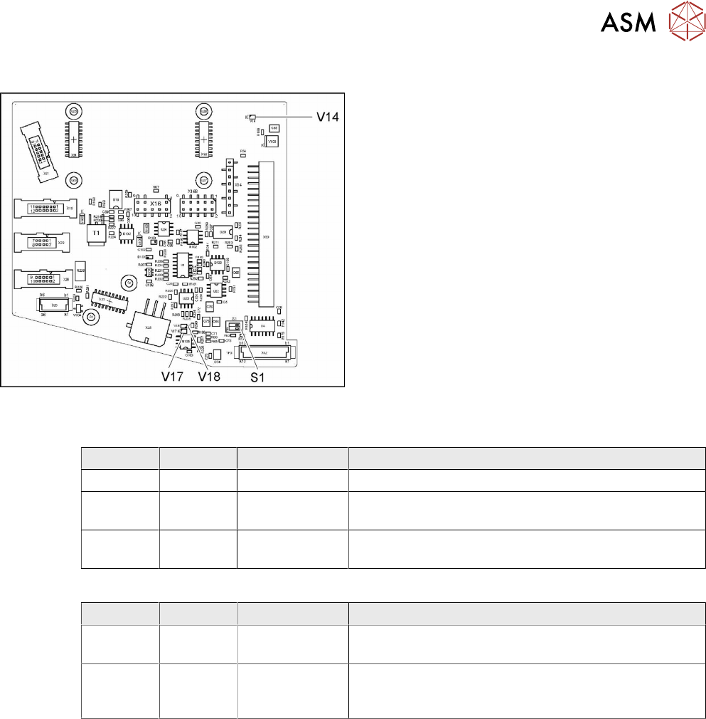
9.2.2 Intermediate distributor ZV2/CPP [03052586-xx]
03052586-03
Intermediate distributor ID2
LED [03052586-03]
LED Color Status Description
V14 YE ON +24VDC_DP_switched
V17 YE ON Potential difference between GND and GND_DP
present
V18 YE ON Potential difference between GND and GND_DP
present
Dip switch S1 [03052586-03]
Switch Status Signal name Description
S1.1 OFF CAN_ID CAN_ID pressure control valve
CAN test – switch over to a cable for head CAN bus
S1.2 OFF CAN_TEST CAN bus test
CAN-ID – set to a fixed CAN ID for the pressure control
valve (for test purposes only)
9 Intermediate distributor and vacuum sensor
9.2 Replacing Intermediate Distributors 1 and 2
112 Service Manual SIPLACE Multistar (CPP / CPP M) 02/2018
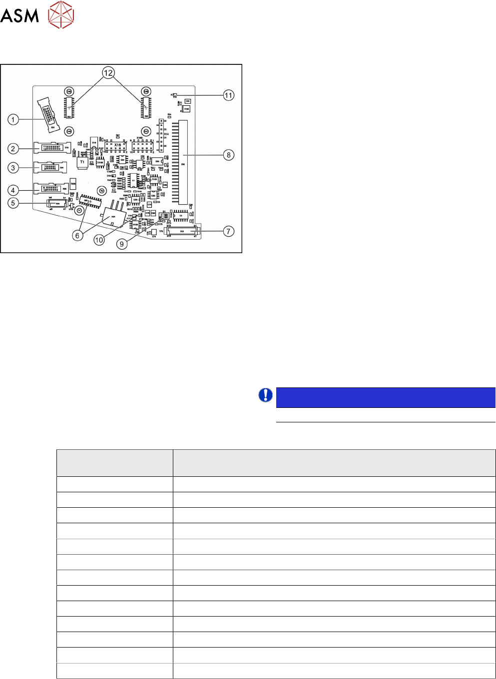
9.2.2.1 Connector Assignment
Fig.185: Connector assignment
The following sensors and actuators for the CPP head
are connected to the intermediate distributor using
press-fit connections:
1. X21 – CO sensor
2. X19 – Vacuum sensor holding circuit
3. X29 – Energy transmission collector ring (24 V)
(CPP head before version 05)
4. X26 Energy transmission (contactless) CPP head
from version 05
5. X20 – Not used
6. X23 – Star encoder connectors (track signals)
with EEPROM, X25 star motor
7. X12 – Digital pressure control valve
8. X30 – Connector to intermediate distributor 1
9. Switch S1.1: CAN test
Switch S1.2: CAN ID
Set both switches to OFF.
10. V17/V18 – Potential display, voltage present
11. 24V – DP 24V switched
12. X31,X32 connector for the KE transmitter control
board (CPP head from version 05)
X14, X16, X16B: Test connector CAN Bus
X27, X28: FPGA test connector
NOTICE!
Either X20, X26 or X29 is used!
.
LEDs
LED
(from left to right)
Meaning
ZU - V106 Z_bottom sensor – LED on = Z_bottom sensor activated
T1 - V113 Output FPGA
T2 - V112 Output FPGA
T3 - V111 Output FPGA
T4 - V110 Output FPGA
T5 - V109 Output FPGA
T6 - V114 Output FPGA
E1 - V107 Input FPGA
E2 - V108 Input FPGA
VAK - V11 LED on = pressure control valve not ready (5V status)
24V - V14 Operating voltage DP axes 24V
V17 Potential display – LED on = voltage present
V18 Potential display – LED on = voltage present