00197463-03_SM_CPP_Customer_EN.pdf - 第112页
9 Intermediate distributor and vacuum sensor 9.2 Replacing Intermediate Distributors 1 and 2 112 Service Manual SIPLACE Multistar (CPP / CPP M) 02/2018 9.2.2.1 Connector Assignment Fig.185: Connector assignment The foll…
9 Intermediate distributor and vacuum sensor
9.2 Replacing Intermediate Distributors 1 and 2
Service Manual SIPLACE Multistar (CPP / CPP M) 02/2018 111
9.2.2 Intermediate distributor ZV2/CPP [03052586-xx]
03052586-03
Intermediate distributor ID2
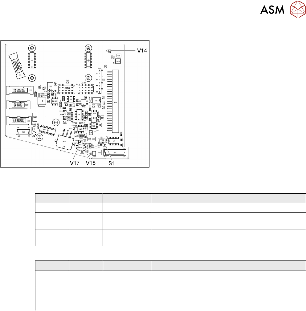
LED [03052586-03]
LED Color Status Description
V14 YE ON +24VDC_DP_switched
V17 YE ON Potential difference between GND and GND_DP
present
V18 YE ON Potential difference between GND and GND_DP
present
Dip switch S1 [03052586-03]
Switch Status Signal name Description
S1.1 OFF CAN_ID CAN_ID pressure control valve
CAN test – switch over to a cable for head CAN bus
S1.2 OFF CAN_TEST CAN bus test
CAN-ID – set to a fixed CAN ID for the pressure control
valve (for test purposes only)
9 Intermediate distributor and vacuum sensor
9.2 Replacing Intermediate Distributors 1 and 2
112 Service Manual SIPLACE Multistar (CPP / CPP M) 02/2018
9.2.2.1 Connector Assignment
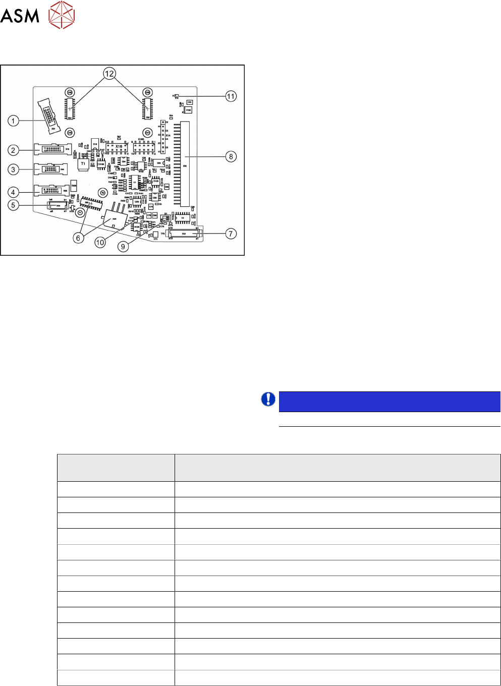
Fig.185: Connector assignment
The following sensors and actuators for the CPP head
are connected to the intermediate distributor using
press-fit connections:
1. X21 – CO sensor
2. X19 – Vacuum sensor holding circuit
3. X29 – Energy transmission collector ring (24 V)
(CPP head before version 05)
4. X26 Energy transmission (contactless) CPP head
from version 05
5. X20 – Not used
6. X23 – Star encoder connectors (track signals)
with EEPROM, X25 star motor
7. X12 – Digital pressure control valve
8. X30 – Connector to intermediate distributor 1
9. Switch S1.1: CAN test
Switch S1.2: CAN ID
Set both switches to OFF.
10. V17/V18 – Potential display, voltage present
11. 24V – DP 24V switched
12. X31,X32 connector for the KE transmitter control
board (CPP head from version 05)
X14, X16, X16B: Test connector CAN Bus
X27, X28: FPGA test connector
NOTICE!
Either X20, X26 or X29 is used!
.
LEDs
LED
(from left to right)
Meaning
ZU - V106 Z_bottom sensor – LED on = Z_bottom sensor activated
T1 - V113 Output FPGA
T2 - V112 Output FPGA
T3 - V111 Output FPGA
T4 - V110 Output FPGA
T5 - V109 Output FPGA
T6 - V114 Output FPGA
E1 - V107 Input FPGA
E2 - V108 Input FPGA
VAK - V11 LED on = pressure control valve not ready (5V status)
24V - V14 Operating voltage DP axes 24V
V17 Potential display – LED on = voltage present
V18 Potential display – LED on = voltage present
9 Intermediate distributor and vacuum sensor
9.3 Replacing the vacuum sensor [03036806-xx]
Service Manual SIPLACE Multistar (CPP / CPP M) 02/2018 113
Addressing the Contactless Energy Transformer
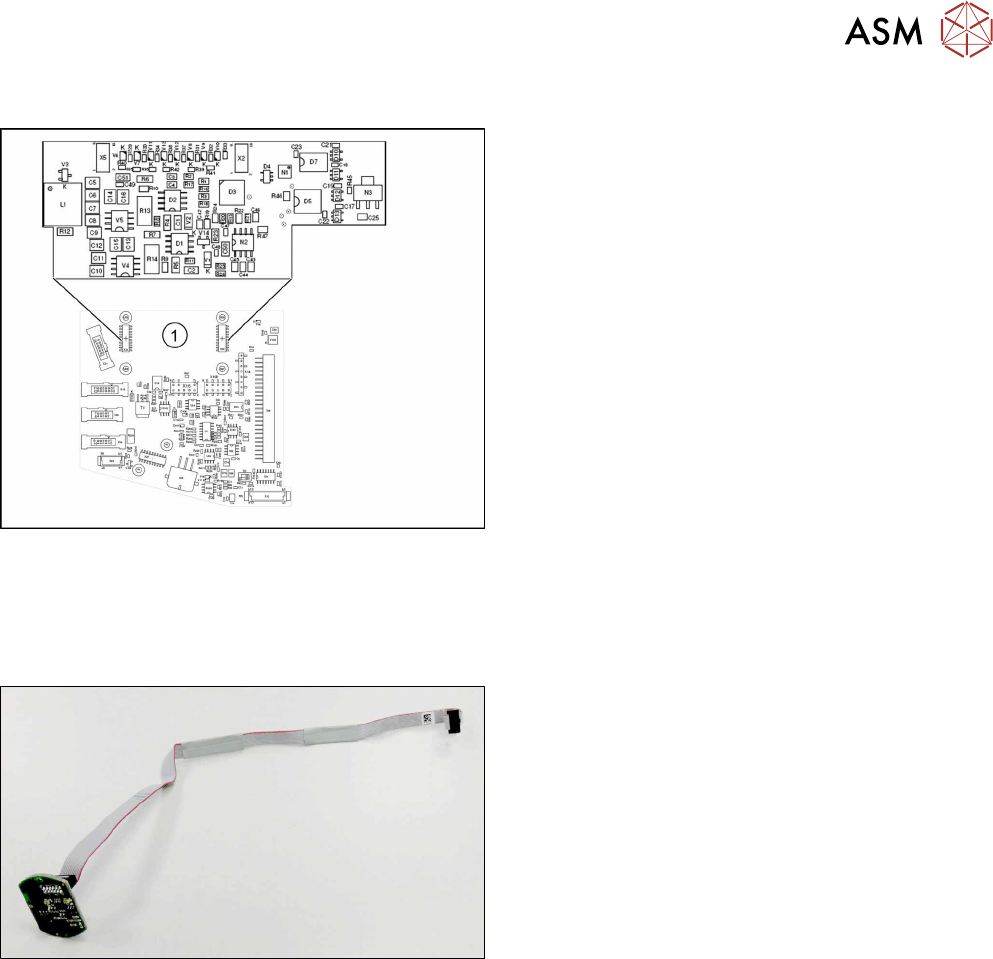
Fig.186: KE transmitter
For contactless energy transmission an additional
board is plugged onto the intermediate distributor 2.
1. X31/X32 - KE transmitter connector terminal
Description of the LEDs:
V6 – maximum current exceeded
V7 – continuous current too high
V9 – KE control switched on
V10 – error, KE transmitter switched off
The green LED V9 lights in normal operation
9.3 Replacing the vacuum sensor [03036806-xx]
Parts, equipment and tools
Fig.187: Vacuum sensor assembly for CPP [03036806-xx]
●
Vacuum sensor assembly for CPP [03036806-xx]
Preparation
► Remove the head from the machine. For details about removing and fitting the placement
head, refer to the service manual for your machine.
fit the head on the head mount [03056231‑xx].
► Make sure that the component sensor protective cap is fitted.
1.1.3 "Protecting the component sensor" [}8]