00197463-03_SM_CPP_Customer_EN.pdf - 第116页
10 Calibration 10.2 Calibration Procedure 116 Service Manual SIPLACE Multistar (CPP / CPP M) 02/2018 Fig.193: Automatic Calibration ► Select Heads and cameras. ► Click on the Continue button. Follow the instructions on …
10 Calibration
10.1 Calibrating the Heads and Cameras (SW70x)
Service Manual SIPLACE Multistar (CPP / CPP M) 02/2018 115
10 Calibration
Overview
With the calibration of the component camera the following values are determined:
the relationship of "camera pixel size to resolution of machine measuring system (X,Y)", the "cam-
era center point in X and Y direction" and the "torsion angle of the CCD sensor in the camera". This
is following by determining the head offset and the segment offsets for the top and bottom.
●
Head offset: the head offset is the distance between the PCB camera and the nozzle (seg-
ment1). The target is a fixed value (X=0 and Y=‑105mm) to which an offset value (from the
head calibration) is added.
●
Segment offset top: the top segment offset involves turning the calibration tool in the compo-
nent camera in 0°, 90°, 180° and 270°. The value determined is that of the rotating center of
the nozzle tip in relation to the component camera center in the X and Y direction.
●
Segment offset bottom: the bottom segment offset involves recording and measuring the
calibration tool in the 0°, 90°, 180° and 270° positions. The value determined is that of the ro-
tating center point of the nozzle tip when the Z axis is extended in relation to the PCB camera.
Segment1 forms the reference (X=0,Y=0) to the other segments.
10.1 Calibrating the Heads and Cameras (SW70x)
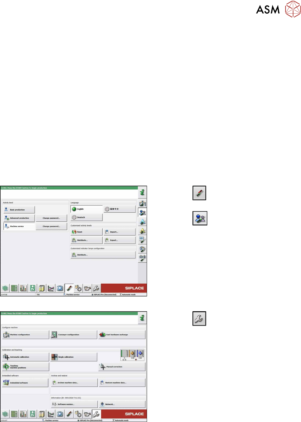
Fig.191: Select operator level
► Click the
button to enter the Settings
menu.
► Click the
button to open the Check and set
user settings menu.
► Switch over to the operator level Machine ser-
vice.
Fig.192: Service Menu
► Click the
button to enter the Service menu.
► Click the Automatic calibration button.
10 Calibration
10.2 Calibration Procedure
116 Service Manual SIPLACE Multistar (CPP / CPP M) 02/2018
Fig.193: Automatic Calibration
► Select Heads and cameras.
► Click on the Continue button.
Follow the instructions on the next pages:
► On the next page, select the gantries on which
the heads to be calibrated are located and then
click on the Next button.
► The next step is to check the calibration condi-
tions (nozzle, calibration tool etc.). Follow the in-
structions provided.
After this step, calibration will begin. All required inter-
mediate steps (head height etc.) will be performed
automatically.
10.2 Calibration Procedure
Fig.194: C&P calibration procedure
10 Calibration
10.3 Calibrating the CO Sensor
Service Manual SIPLACE Multistar (CPP / CPP M) 02/2018 117
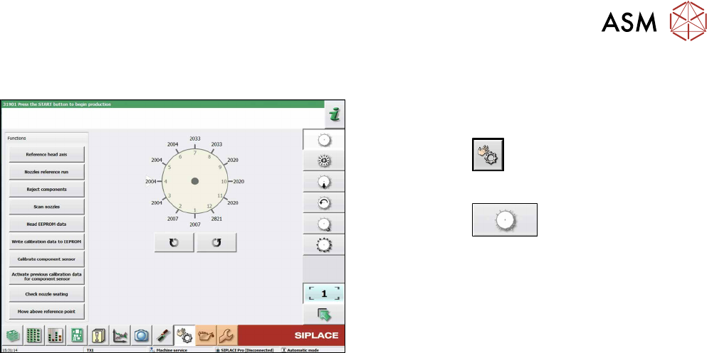
10.3 Calibrating the CO Sensor
Fig.195: Calibrating the component sensor (example of
SIPLACE CPP shown)
► Switch over to the operator level Machine Ser-
vice.
► Click on the
button.
► Select the head.
► Click on the
button.
► Click on the Calibrate component sensorbu-
tton.