00197463-03_SM_CPP_Customer_EN.pdf - 第17页
2 Overview of the Modules 2.1 CPP Head Service Manual SIPLACE Multistar (CPP / CPP M) 02/2018 17 2 Overview of the Modules 2.1 CPP Head Fig.4: SIPLACE CPP with camera SIPLACE CPPM [03153719Sxx] SIPLACE CPP with camera …

1 Introduction
1.5 Tools required, measuring equipment and materials
16 Service Manual SIPLACE Multistar (CPP / CPP M) 02/2018
2 Overview of the Modules
2.1 CPP Head
Service Manual SIPLACE Multistar (CPP / CPP M) 02/2018 17
2 Overview of the Modules
2.1 CPP Head
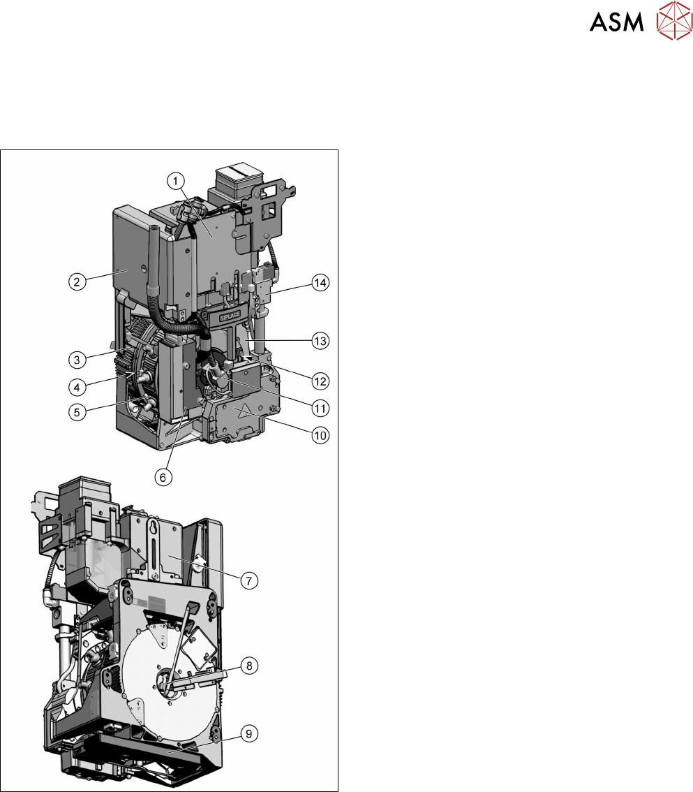
Fig.4: SIPLACE CPP with camera
SIPLACE CPPM [03153719Sxx]
SIPLACE CPP with camera SST29 [03070108‑xx]
SIPLACE CPP without camera [03053528‑xx]
1. Intermediate distributor 1 (ID1)
2. Intermediate distributor 2 (ID2) and
KE control board ID2
(under the cover)
9.2 "Replacing Intermediate Distributors 1
and 2" [}107]
9.1 "Replacing the KE Control Board ZV2
[03073355-xx]" [}105]
3. Star motor (integrated in head housing)
5.2 "Removing and fitting the star (only for heads
from FS05 upwards)" [}43]
4. Smoothed distributor disc (between star motor
and star)
5.3 "Replacing the smoothed distributor disc
[03055431-xx]" [}47]
5. Star with DP drives
6 "DP drives" [}71]
6. Pressure control valve (PRV)
7 "Pressure control valve (PRV)" [}79]
7. Component camera
4.1 "Replacing the component camera
[03018637‑xx]" [}29]
8. Vacuum sensor
9.3 "Replacing the vacuum sensor
[03036806-xx]" [}113]
9. Component sensor in the pick and place position
(on the underside)
4.2 "Replacing the component sensor
[03037106-xx]" [}32]
4.3 "Replacing the component sensor cable
[03063595-xx]" [}33]
10. Z axis
11. Holding circuit supply, integrated venturi nozzles
and valve assembly (valve terminal)
8 "Screwed joint, silencer and holding cir-
cuit" [}93]
12. Single core solution (SCS) – DP drive control
5.5 "Replacing the Single Core Solution (SCS)
[03054790Sxx] (only for heads
fromFS05)" [}
53]
13. Front plate
5.1 "Replacing the front plate [03061102-
xx]" [}35]
14. Return cylinder
2 Overview of the Modules
2.1 CPP Head
18 Service Manual SIPLACE Multistar (CPP / CPP M) 02/2018
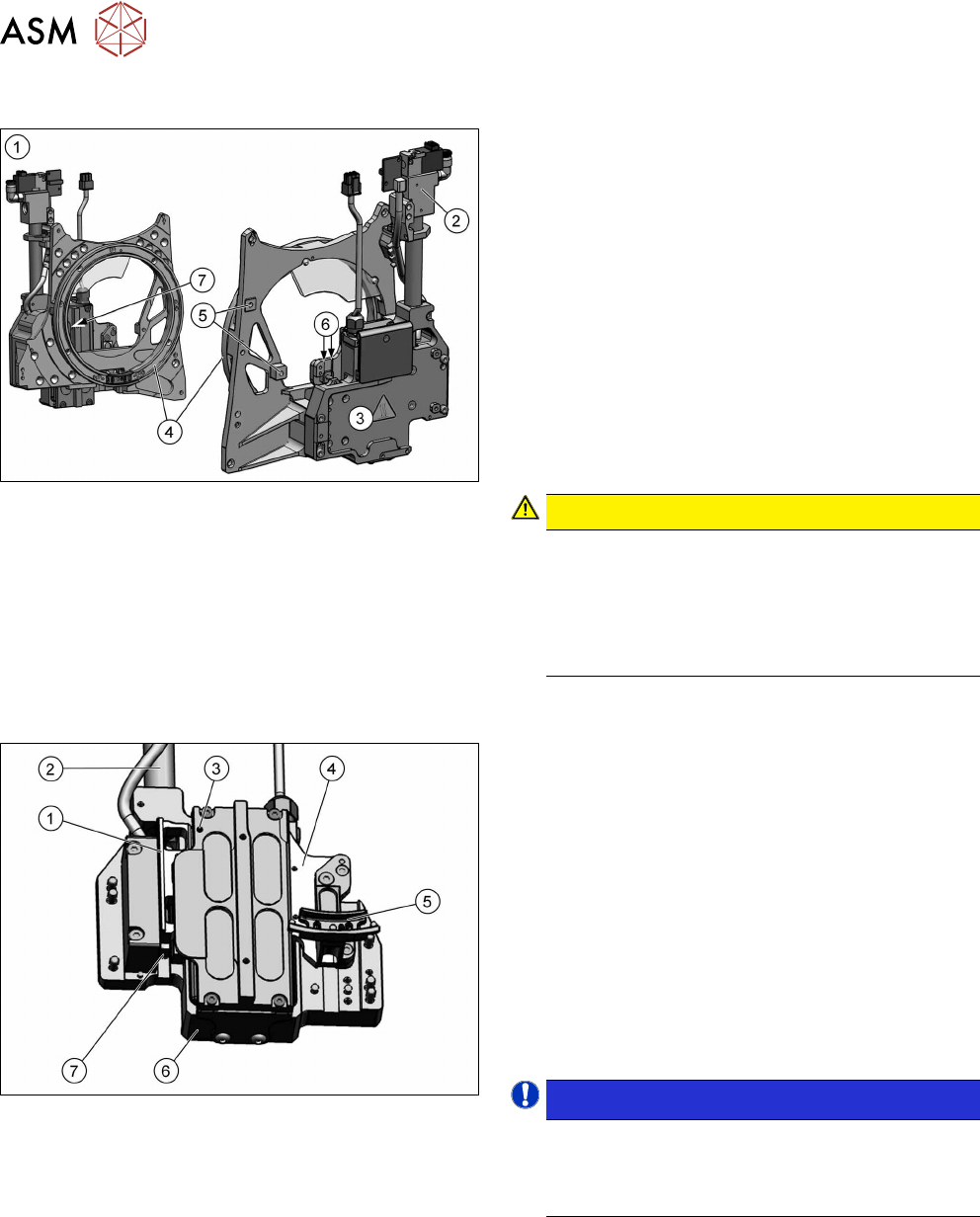
2.1.1 Front plate
Fig.5: Front plate
1. Front plate
2. Return cylinder
3. Z axis with jaws and measuring system
4. Raceway
5. Fixture for pressure control valve
6. Lubrication linear guidance Z axis
7. Lubrication service hole support roller – Z axis
(not present for all head versions. See 2.1.2 "Z
Axis" [}18])
The front plate of the CPP head is fixed to the head
housing with four screws and can be removed as a
whole unit for service purposes.
CAUTION!
Do not dismantle any attachments
Do not dismantle (remove) any parts attached to
the front plate, unless it is explicitly permitted. All
attachments are coordinated with one another
and require special settings (except the pressure
control valve).
.
2.1.2 Z Axis
Fig.6: Z-axis
1. Incremental measurement system, resolution
0.5µm
2. Return unit
3. Service hole for lubricating the Z axis support
roller
4. Secondary part with magnets
The secondary part is fitted to the Z axis.
5. Jaws
The jaws are fitted to the linear guidance of the
Z axis.
6. Linear motor, primary part
7. Actuator on the return unit
NOTICE!
If there is no yellow dot at the position (3) and no
service hole for oiling the support roller then
there is no need to oil it. See also the preventive
maintenance manual of your machine.
.