00197463-03_SM_CPP_Customer_EN.pdf - 第23页
2 Overview of the Modules 2.1 CPP Head Service Manual SIPLACE Multistar (CPP / CPP M) 02/2018 23 2.1.8 Single Core Solution (SCS) Fig.14: SCS 1. Board control module 2. Board power module 3. Carrier plate 4. Connector (…
2 Overview of the Modules
2.1 CPP Head
22 Service Manual SIPLACE Multistar (CPP / CPP M) 02/2018
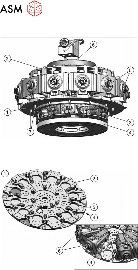
2.1.6 Star
Fig.12: Star (from FS05)
1. Star carrier
2. Single Core Solution (SCS).
3. Valve terminal
4. Contact-free energy and data transmitter
5. DP drives
6. Holding circuit in the middle of the star
7. Fixture on rotor of star motor
The star consists of the star carrier, on which all
twelve DP drives are located, the control board (SCS),
the valve terminal, an energy and a data transmitter.
The holding circuit is in the center of the star
The complete unit is fixed to the rotor of the star mo-
tor.
2.1.7 Star Frame
Fig.13: Star carrier
1. Star carrier
2. Star carrier plate
3. Hose to DP drive
4. Back of the star carrier
5. Front of the star carrier
6. DP drive
The star carrier plate is fixed directly to the rotor of the
star motor.
The valve terminal and the energy and data trans-
former are fixed to the back of the star carrier.
The twelve DP drives are fixed to the front and the
holding circuit with control unit SCS is fixed to the cen-
ter.
The air blast (component reject) and the vacuum
(component pickup) are run via the pressure control
valve, the smoothed distributor disc and the outer
valve terminal holes, through the star carrier plate via
a hose to the individual DP drives.
2 Overview of the Modules
2.1 CPP Head
Service Manual SIPLACE Multistar (CPP / CPP M) 02/2018 23
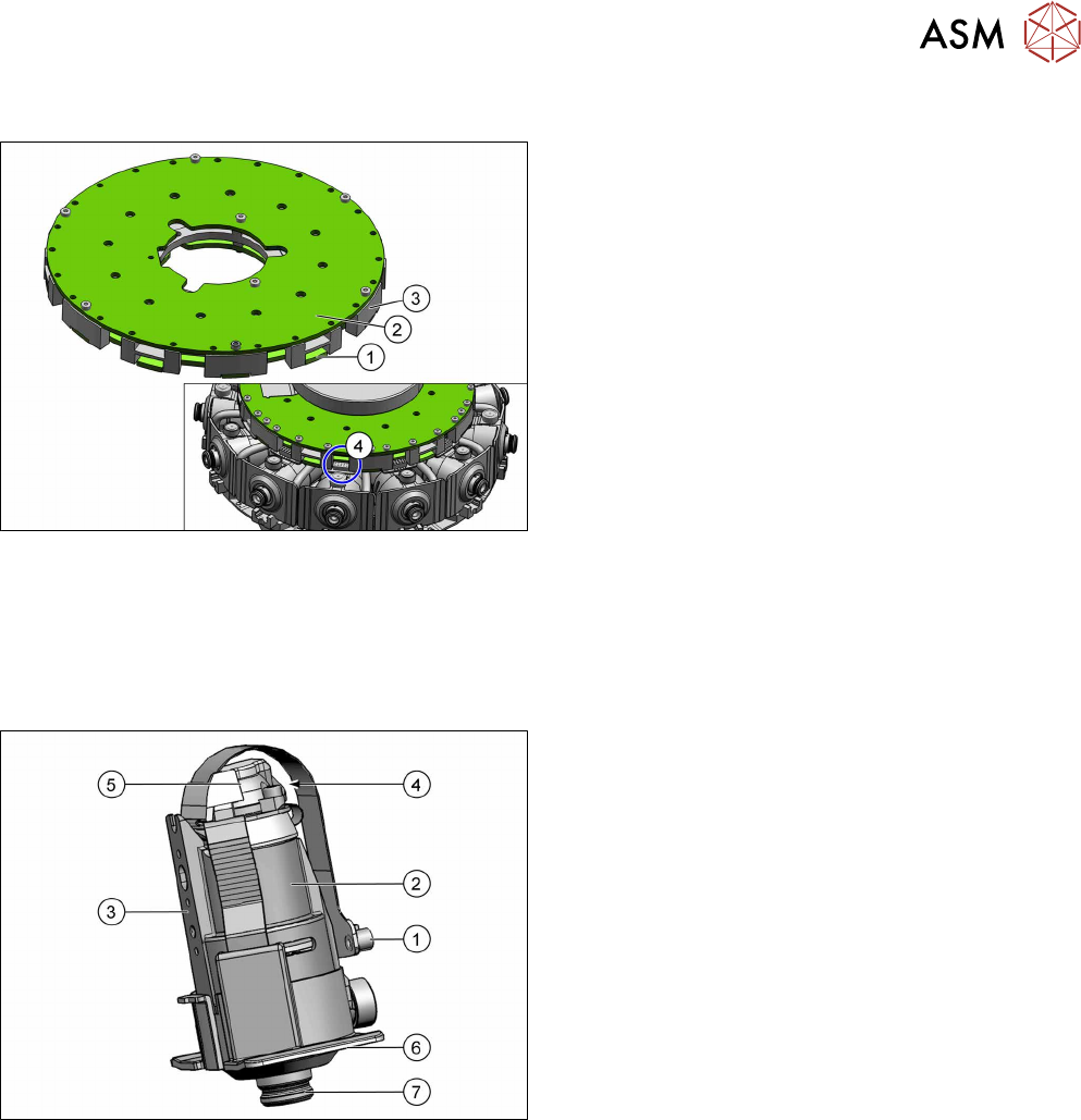
2.1.8 Single Core Solution (SCS)
Fig.14: SCS
1. Board control module
2. Board power module
3. Carrier plate
4. Connector (control unit) for energy and data sup-
ply to the DP drives
The SCS has two main tasks:
1. Controlling the DP drives
2. Evaluating the Z down light barrier.
The SCS consists of a carrier plate and two boards
(control module and power module).
The energy and data supply is via the head CAN bus
from the intermediate distributor, energy and data
transformer to the SCS.
The SCS features twelve connectors, which establish
the connection for the energy and data supply to the
DP drives.
2.1.9 DP drive
Fig.15: DP drive
1. The connector is fitted and screwed to the SCS
control unit.
2. Motor
3. Fixture surface for screwing the linear guidance
into place
4. Vacuum connection.
5. Measuring system
Resolution: 278digitsperdegree or
100,000digitsperrevolution
6. Camera background (black) for DP drive
7. Nozzle interface
The DP drive is responsible for turning the nozzles into
the correct pickup position and the component into the
correct placement position.
The holding circuit vacuum and air blast plus the pres-
sure control valve vacuum are made available at the
nozzle, via the DP drive motor shaft.
2 Overview of the Modules
2.1 CPP Head
24 Service Manual SIPLACE Multistar (CPP / CPP M) 02/2018
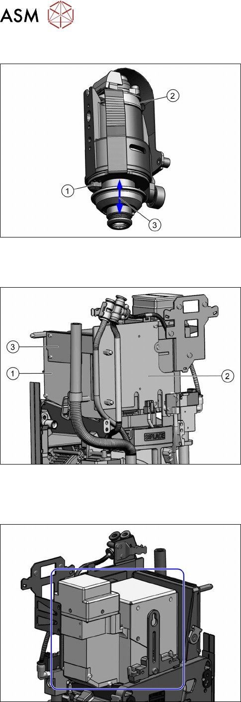
2.1.9.1 DP drive function
Fig.16: DP drive function
1. Light barrier down
2. Measuring system
3. Cushioning path for operating the light barrier
down
The DP drives are controlled by the SCS board, in
accordance with the counter pulse and nominal value
(pickup angle, placement angle and correction angle
after Vision).
The feedback about the position of the DC motor is
monitored by an incremental measuring system.
2.1.10 Intermediate distributor 1 and 2 (ID1 and ID2)
Fig.17: Intermediate distributor (from version 05)
1. Intermediate distributor 1
2. Intermediate distributor2
3. KE control board ID2 for contactless data trans-
mission (from version 05)
Intermediate distributor function:
●
LEDs show the operating voltages at the head
and the sensor states
●
Test connector for the track signals and test pins
for analog signals
●
Controlled power supply for incremental encoder
from Z and star drive
●
Interface for component sensor, vacuum unit, va-
cuum sensor of holding circuit and EEPROM
●
Startup control for the return cylinder
2.1.11 Component camera
Fig.18: Component camera
Component camera
Available types:
●
SST23
●
SST29
●
SST30
●
SST38
●
SST45
The component camera is fitted in the 12 o'clock posi-
tion.
This camera is responsible for optically recognizing
the component and for calculating its centerpoint.
The component camera evaluates the data determ-
ined and calculates the offset between the component
centerpoint and the nozzle centerpoint plus the angle
in the placement position.