00197463-03_SM_CPP_Customer_EN.pdf - 第31页
4 Component camera and component sensor 4.1 Replacing the component camera [03018637‑xx] Service Manual SIPLACE Multistar (CPP / CPP M) 02/2018 31 Installation ► Follow the removal instructions in reverse order for insta…
4 Component camera and component sensor
4.1 Replacing the component camera [03018637‑xx]
30 Service Manual SIPLACE Multistar (CPP / CPP M) 02/2018
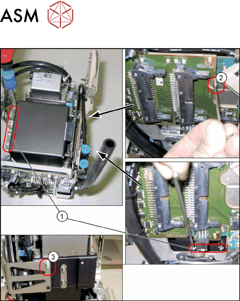
Fig.30: Fixture points for component camera
1. Screws at the foot of the camera 4x)
DIN912-M3x16-A2-70 [00325349-xx]
2. Screw on the board holder (1x)
ISO4762-M2.5x4-A2-70 [03042531-xx]
DIN125-A2.7-140HV-A2 [00201583-xx]
3. Screw on the retaining bracket (1x)
ISO 4762 - M 2.5 x 4-A2-70 [03042531-xx ]
DIN 125-A 2.7-140HV-A2 [00201583-xx]
Preparation
► Remove the head from the machine. For details about removing and fitting the placement
head, refer to the service manual for your machine.
fit the head on the head mount [03056231‑xx].
► Make sure that the component sensor protective cap is fitted.
1.1.3 "Protecting the component sensor" [}8]
Removal
► Open the cable holders for the component camera cable.
► Remove the six screws fastening the component camera.
(4x on the camera base, 1x on the board holder, 1x on the retaining bracket)
► Carefully pull the component camera off the locating pins.
4 Component camera and component sensor
4.1 Replacing the component camera [03018637‑xx]
Service Manual SIPLACE Multistar (CPP / CPP M) 02/2018 31
Installation
► Follow the removal instructions in reverse order for installation. Also observe the following in-
structions:
CAUTION
Installation instructions
► Make sure that you do not damage or contaminate the camera lens system.
► Tighten the fourscrews fastening the component camera base with a torque of 2Nm
and the other two screws hand-tight.
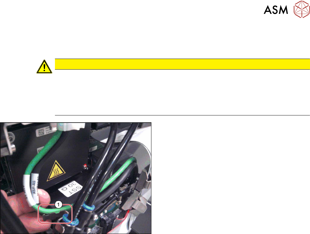
► Make sure that the GigE cable is run correctly (see below).
Fig.31: Fastening the GigE cable
Only heads with GigE:
► Use cable ties to fasten the GigE cable to the fix-
ture(1) (if present).
4 Component camera and component sensor
4.2 Replacing the component sensor [03037106-xx]
32 Service Manual SIPLACE Multistar (CPP / CPP M) 02/2018
4.2 Replacing the component sensor [03037106-xx]
Parts, equipment and tools
●
CPP component sensor [03037106-xx]
Overview
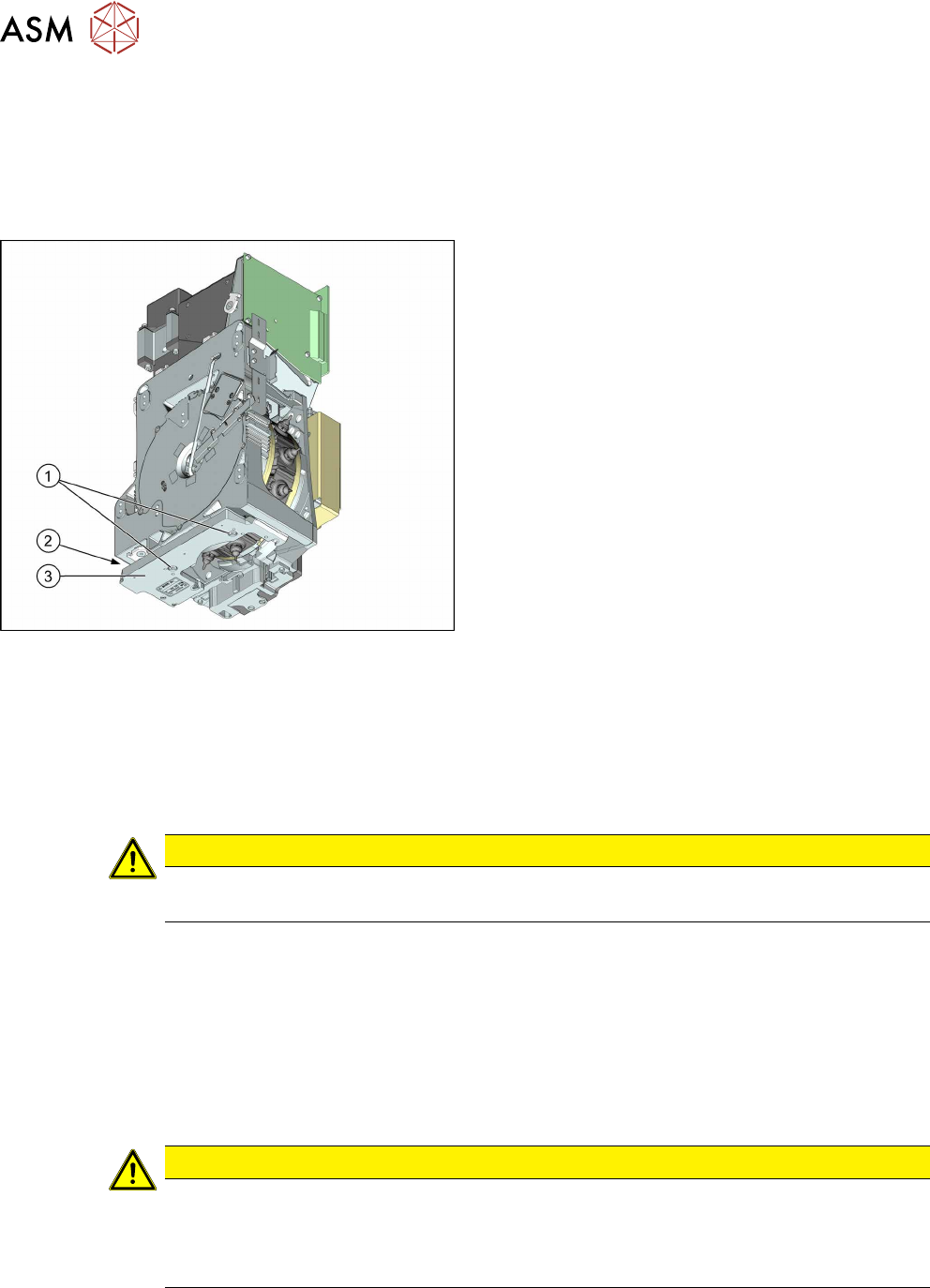
Fig.32: BE sensor
1. Fastening screws for component sensor
2. Connector
3. Component sensor
As a default, each CPP head is fitted with a compo-
nent sensor in the pickup/place position.
The component sensor monitors the presence and/or
component height after pickup and before placement.
Preparation
► Remove the head from the machine. For details about removing and fitting the placement
head, refer to the service manual for your machine.
fit the head on the head mount [03056231‑xx].
Removal
CAUTION
Prisms on the component sensor
Take care not to damage the component sensor prisms.
► Unplug the connector from the component sensor by pressing the sides of it together slightly.
This releases the catch in the connector.
► Remove the two fastening screws.
► Carefully pull the connector off.
Installation
► Follow the removal instructions in reverse order for installation. Also observe the following in-
structions:
CAUTION
Installation instructions
► Tighten the screws fastening the component sensor with a torque of 1.45Nm.
► To place components smaller than 0201, you need to calibrate the component sensor.
For more information, read section 10.3 "Calibrating the CO Sensor" [}117].