00197463-03_SM_CPP_Customer_EN.pdf - 第56页
5 Front plate, star, Z axis and smoothed distributor disc 5.5 Replacing the Single Core Solution (SCS)[03054790Sxx] (only for heads fromFS05) 56 Service Manual SIPLACE Multistar (CPP / CPP M) 02/2018 Installation Fig.8…
5 Front plate, star, Z axis and smoothed distributor disc
5.5 Replacing the Single Core Solution (SCS)[03054790Sxx] (only for heads fromFS05)
Service Manual SIPLACE Multistar (CPP / CPP M) 02/2018 55
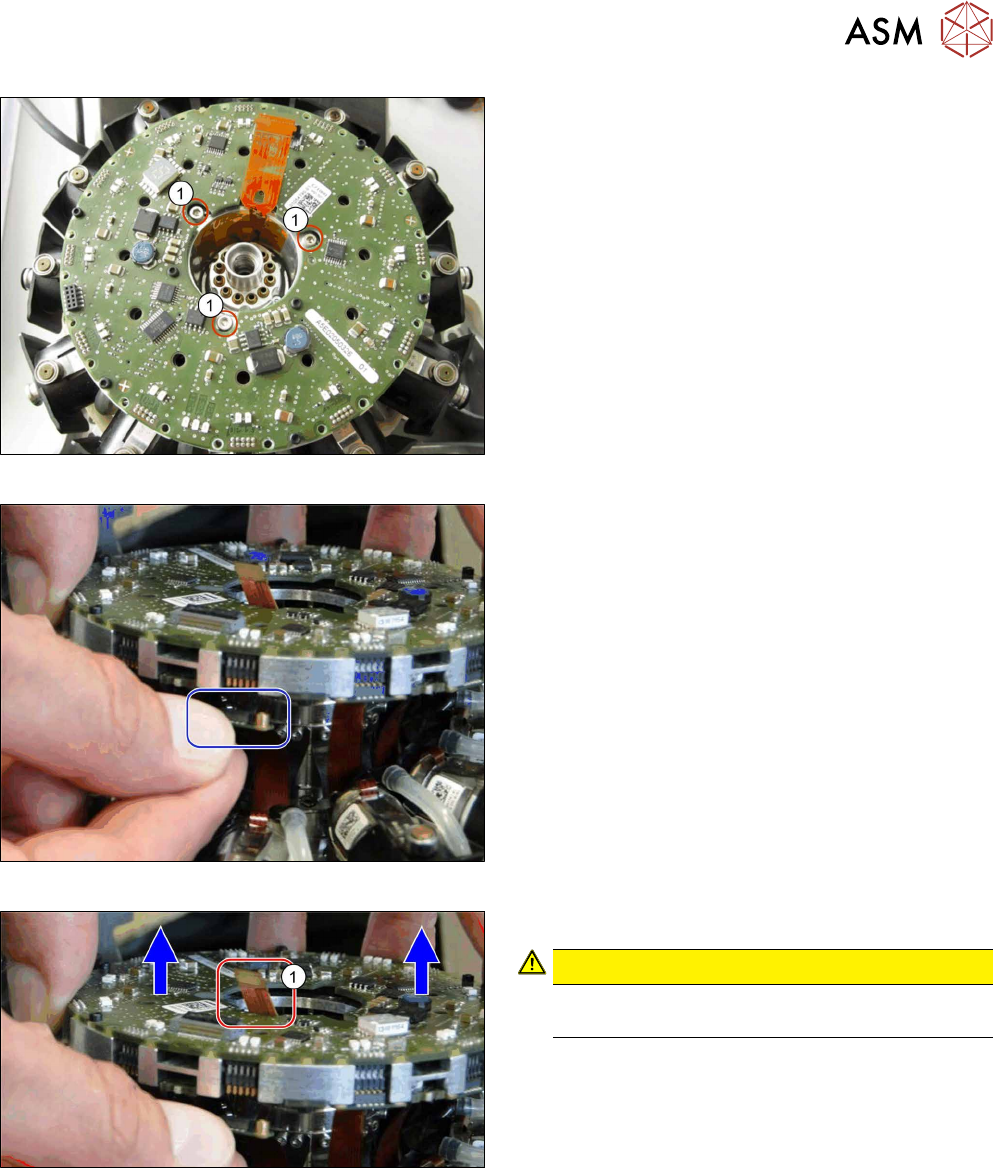
Fig.82: Removing the screws fastening the SCS
► Remove the three screws(1) fastening the SCS.
Fig.83: Unplug the connector
► Unplug the connectors from all twelve DP drives.
You can lift the SCS slightly, if needed.
Fig.84: Lifting out the SCS
► Carefully lift the SCS up and out of the head.
CAUTION!
Take care not to damage the Flexprint
cable(1) in the middle.
.
5 Front plate, star, Z axis and smoothed distributor disc
5.5 Replacing the Single Core Solution (SCS)[03054790Sxx] (only for heads fromFS05)
56 Service Manual SIPLACE Multistar (CPP / CPP M) 02/2018
Installation
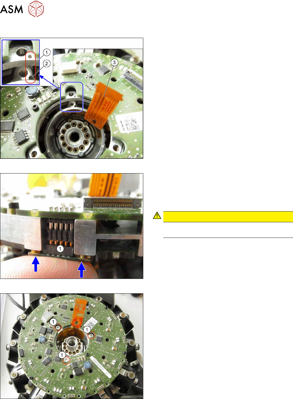
Fig.85: Inserting the SCS
► Carefully insert the new SCS.
Make sure that the pin(1) in the SCS is correctly
positioned in the hole(2) in the bottom part.
Also pay attention to the correct connection of the
Flexprint cable(3) to the relevant connector.
Fig.86: Connecting the plugs
► Attach the connectors(1) of all twelve DP drives
to the SCS.
Press the connector into position with your finger,
until the connector engages.
You can also lift the SCS slightly, if needed.
CAUTION!
Take care not to damage the Flexprint cable
for the DP drives.
.
Fig.87: Fastening the SCS
► Fasten the SCS with three screws.
Torque: 0.4Nm
5 Front plate, star, Z axis and smoothed distributor disc
5.5 Replacing the Single Core Solution (SCS)[03054790Sxx] (only for heads fromFS05)
Service Manual SIPLACE Multistar (CPP / CPP M) 02/2018 57
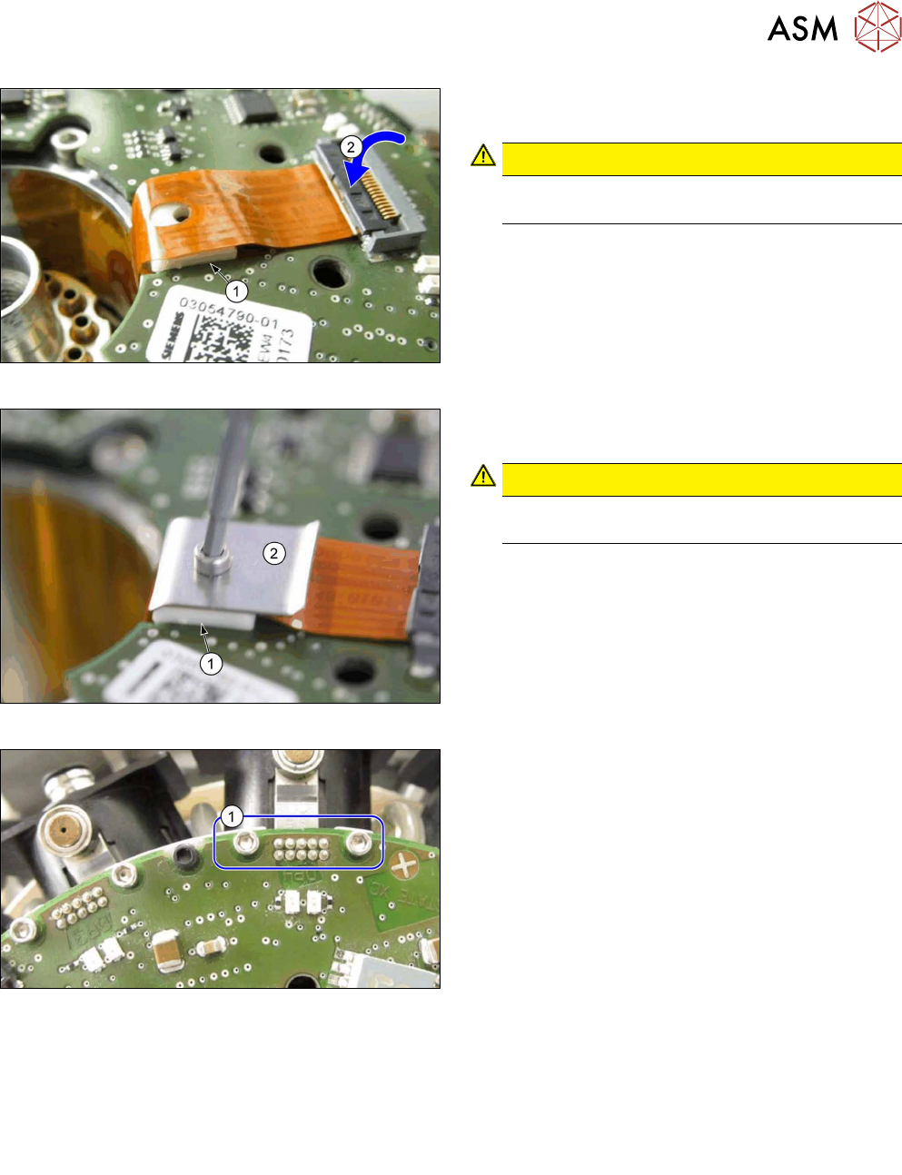
Fig.88: Connecting the Flexprint cable
► Place the white mat(1) into the SCS recess, un-
der the Flexprint cable.
CAUTION!
Pay attention to the correct installation posi-
tion of the white mat(1).
.
► Insert the Flexprint cable contact shoe into the
connector(2) and lock it.
Fig.89: Fitting the strain relief
► Fit the strain relief for the Flexprint cable.
Hand-tighten the screw.
CAUTION!
Pay attention to the correct installation posi-
tion of the mat(1) and the cover (2).
.
Fig.90: Fastening the connector with screws
► For all twelve drives: fit both screws(1), which
fasten the connectors to the Flexprint cables on
the SCS.
Torque: 0.1Nm
► Follow the removal instructions in reverse order for further installation.
Also observe the installation instructions in the following sections:
8.4 "Replacing the holding circuit" [}101]
5.2 "Removing and fitting the star (only for heads from FS05 upwards)" [}43]
5.1 "Replacing the front plate [03061102-xx]" [}35]
► Observe in particular the torques specified!