00197463-03_SM_CPP_Customer_EN.pdf - 第78页
6 DP drives 6.4 Calibrating the segment offset 78 Service Manual SIPLACE Multistar (CPP / CPP M) 02/2018
6 DP drives
6.4 Calibrating the segment offset
Service Manual SIPLACE Multistar (CPP / CPP M) 02/2018 77
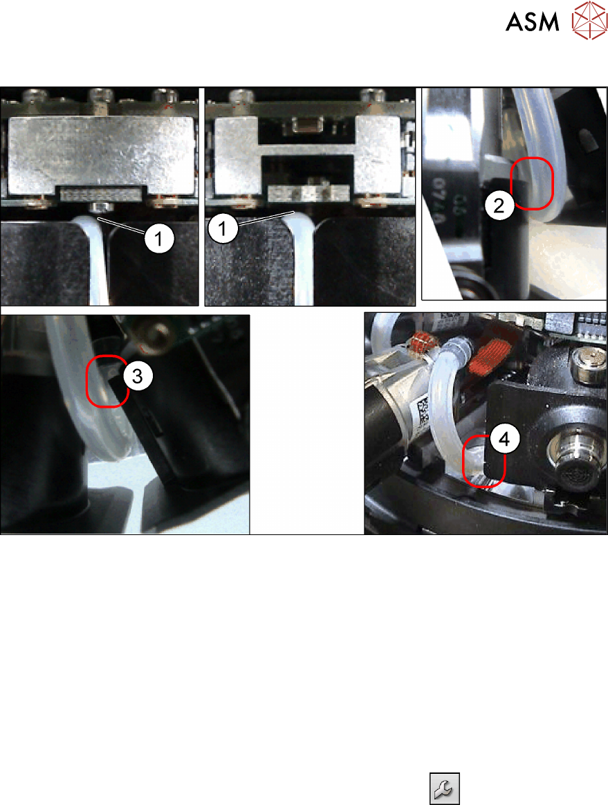
Possible points of rubbing
Fig.119: Check possible points of rubbing
► Make sure that the hose is run without obstructions. Check in particular the possible points of
rubbing described.
Check how the hose is run by moving out the entire DP drive.
If the vacuum hose rubs at any of the points described (1) to (4), turn the hose accordingly at
the star carrier or DP drive.
See also
2 6.1 "Replacing the DP drives" [}71]
6.4 Calibrating the segment offset
► Switch over to operator level SIPLACE (customer).
► Select Service (configure, update and calibrate the machine)
.
► Select Single calibration.
► Select Head calibration.
► Select Calibrate segments...
► Select the segments to be calibrated and then click on Start calibration.

6 DP drives
6.4 Calibrating the segment offset
78 Service Manual SIPLACE Multistar (CPP / CPP M) 02/2018
7 Pressure control valve (PRV)
7.1 Replacing the PRV [03072785‑xx]
Service Manual SIPLACE Multistar (CPP / CPP M) 02/2018 79
7 Pressure control valve (PRV)
7.1 Replacing the PRV [03072785‑xx]
Parts, equipment and tools
●
CPP pressure control valve [03072785-xx] (replaces: [03055438-xx])
Overview
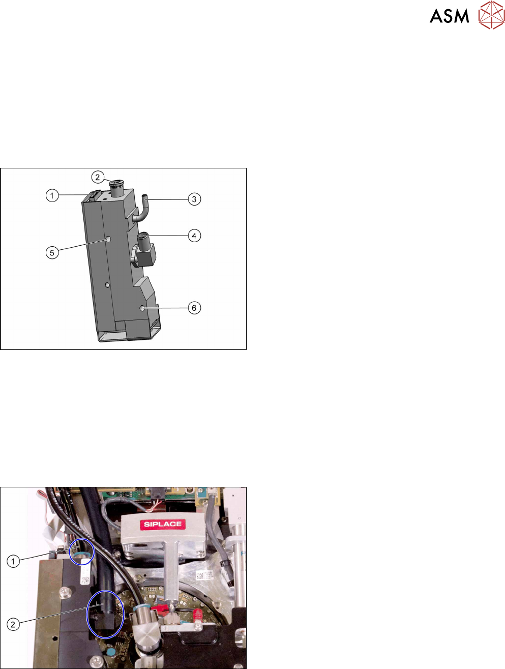
Fig.120: Pressure control valve (PRV)
1. Energy and data supply
2. Compressed air connection
3. Vacuum/air blast output for pickup/placement cir-
cuit
4. Exhaust air, for cooling the X linear motor
5. Top fastening screw M4x35
6. Bottom fastening screw M4x30
The PRV supplies the pickup/placement circuit with
vacuum during the pickup process and switches over
to air blast during placement.
The digital pressure control valve can be adjusted in-
finitely between max. vacuum and max. air blast in the
pickup / placement circuit.
Preparation
► Remove the head from the machine. For details about removing and fitting the placement
head, refer to the service manual for your machine.
fit the head on the head mount [03056231‑xx].
► Make sure that the component sensor protective cap is fitted.
1.1.3 "Protecting the component sensor" [}8]
Removal
Fig.121: Hoses 1
► Disconnect the compressed air hose(1).
► Disconnect the exhaust air hose(2).