TR7007SII_Hardware_ch-v1-0-1 - 第44页
Test Research Inc. 32 TR 7007 SII User Guide – Hardwa re 圖 76 : 人機介面 – PLC 程式更換 – 開新檔案 6) 點擊選單中的圖示 (Dow nload to PLC ) ,點選 [ 是 ] ,確認覆蓋現有的程式。 圖 77 : 人機介面 – PLC 程式更換 – Download to P LC
Test Research Inc.
TR7007 SII User Guide – Hardware 31
圖
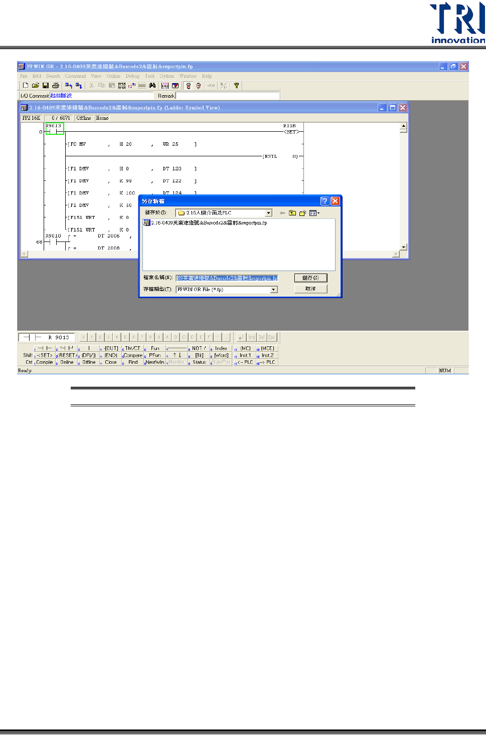
75:
人機介面
–PLC
程式更換
–
備份舊檔
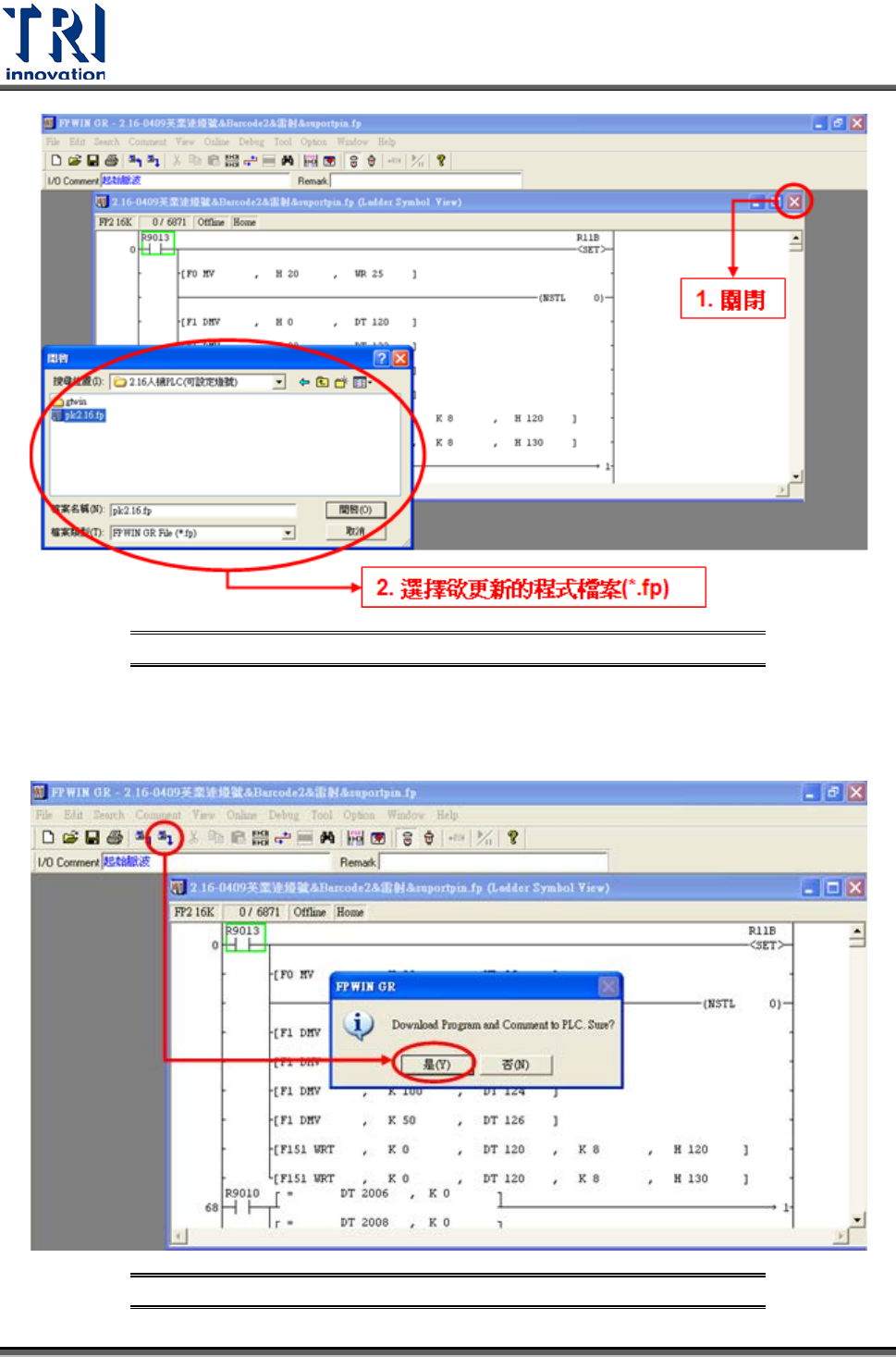
5) 備份後,將原本的 PLC 程式關閉,再點擊[File]選擇[Open]開啟欲更新的 PLC 程
式(*.fp)。
Test Research Inc.
32 TR7007 SII User Guide – Hardware
圖
76:
人機介面
–PLC
程式更換
–
開新檔案
6) 點擊選單中的圖示 (Download to PLC),點選[是],確認覆蓋現有的程式。
圖
77:
人機介面
–PLC
程式更換
–Download to PLC
Test Research Inc.
TR7007 SII User Guide – Hardware 33
7) 等候 PC 傳輸資料至 PLC 後,程式即可更新完成。
3.6 PLC
硬體簡介
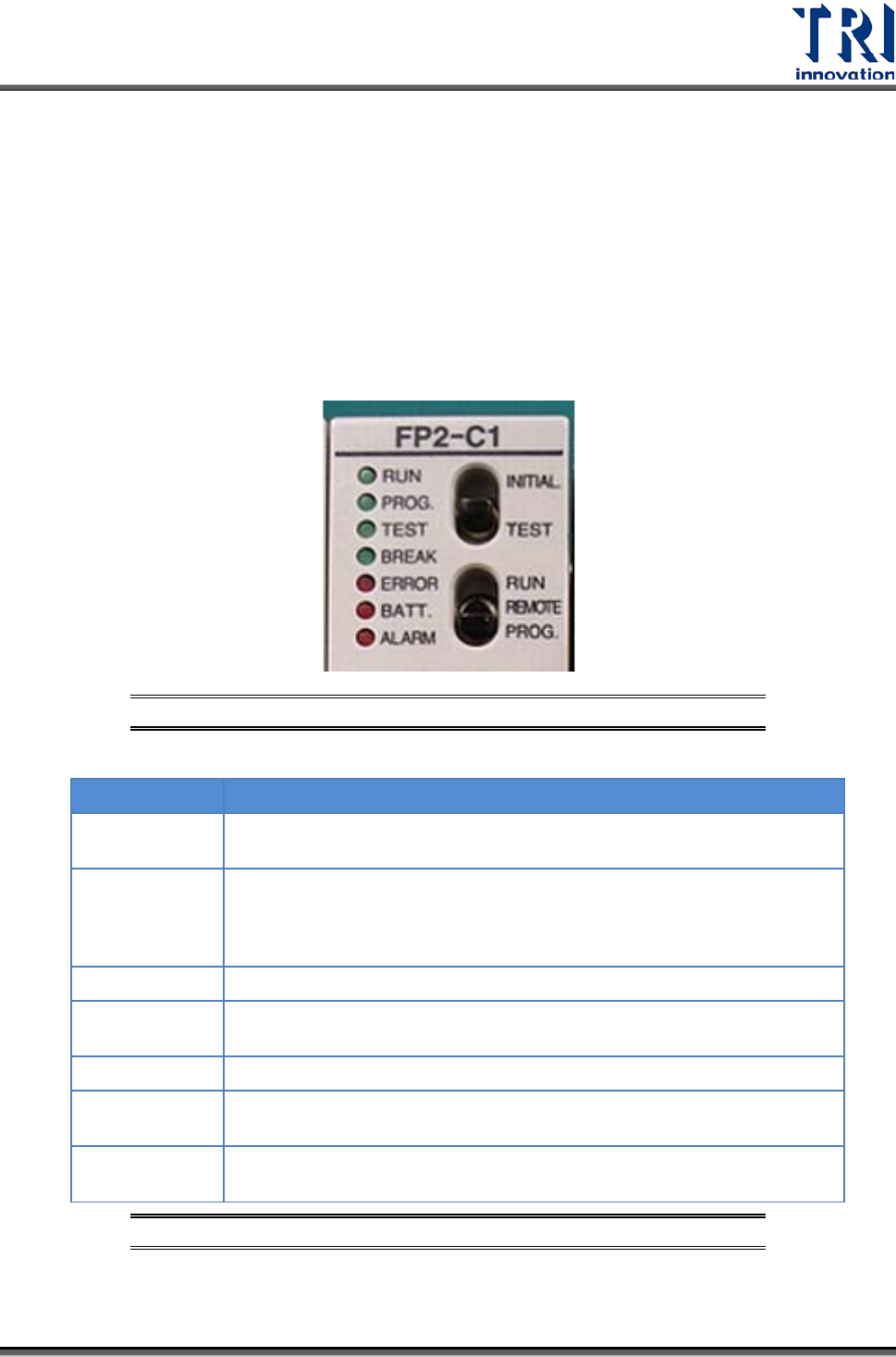
3.6.1 CPU(FP2-C1)
單元
Status indicator LEDs
圖
78: PLC’s CPU LEDs & Switches
LED
DESCRIPTION
RUN (green)
This lights in the RUN mode, to indicate that the program is begin
executed. It flashes during forced input/output.
PROG. (green)
This lights in the PROG. mode. Operation stops while this LED is lighted.
It flashes when waiting for connection of slave station on remote I/O
system. If the memory is initialized, the brightness dims, indicating that
initialization is being executed.
TEST (green)
This lights in the test operation mode.
BREAK (green)
This lights in the operation halts at a break during a test run or halts
during the step operation mode for the test run.
ERROR (red)
This lights if an error is detected during the self-diagnostic function.
BATT. (red)
This lights when the voltage of the backup battery drops below a specific
value.
ALARM (red)
This lights if a hardware error occurs, or if operation slows because of the
program, and the watchdog timer is activated.
圖
79: CPU(FP2-C1)
單元
–Status indicator LEDs