TR7007SII_Hardware_ch-v1-0-1 - 第45页
Test Research Inc. TR 7007 SII User Guide – Hardwa re 33 7) 等候 PC 傳輸資料至 PLC 後,程式即可更新完成。 3.6 PLC 硬體簡介 3.6.1 CPU(FP2 - C1) 單元 Status i ndicator LEDs 圖 78 : PLC’s C PU L EDs & Sw itc hes LED D ESCRI PTION RUN (gree n)…
Test Research Inc.
32 TR7007 SII User Guide – Hardware
圖
76:
人機介面
–PLC
程式更換
–
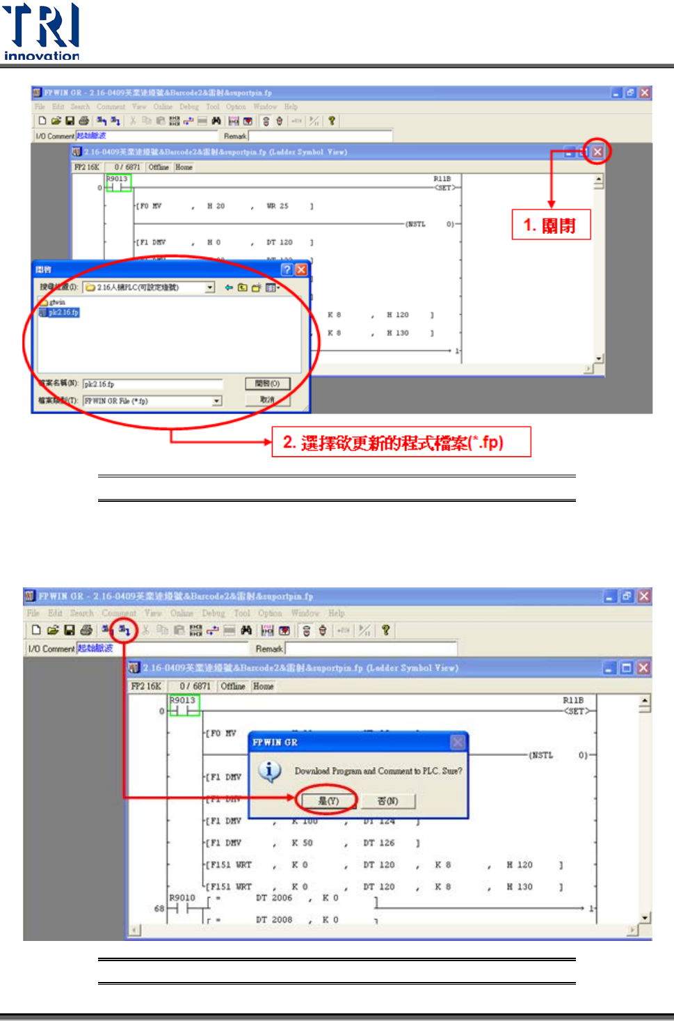
開新檔案
6) 點擊選單中的圖示 (Download to PLC),點選[是],確認覆蓋現有的程式。
圖
77:
人機介面
–PLC
程式更換
–Download to PLC
Test Research Inc.
TR7007 SII User Guide – Hardware 33
7) 等候 PC 傳輸資料至 PLC 後,程式即可更新完成。
3.6 PLC
硬體簡介
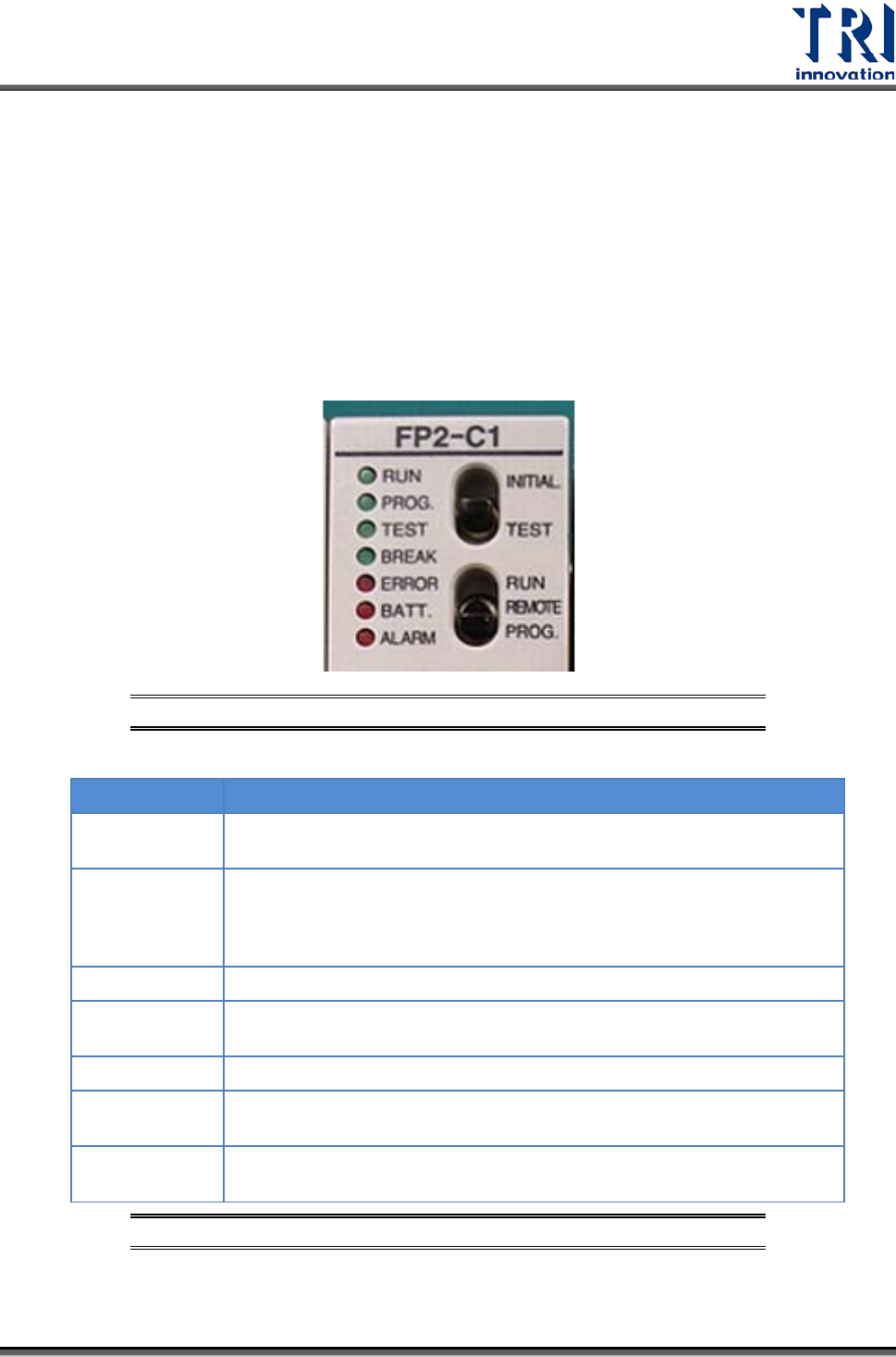
3.6.1 CPU(FP2-C1)
單元
Status indicator LEDs
圖
78: PLC’s CPU LEDs & Switches
LED
DESCRIPTION
RUN (green)
This lights in the RUN mode, to indicate that the program is begin
executed. It flashes during forced input/output.
PROG. (green)
This lights in the PROG. mode. Operation stops while this LED is lighted.
It flashes when waiting for connection of slave station on remote I/O
system. If the memory is initialized, the brightness dims, indicating that
initialization is being executed.
TEST (green)
This lights in the test operation mode.
BREAK (green)
This lights in the operation halts at a break during a test run or halts
during the step operation mode for the test run.
ERROR (red)
This lights if an error is detected during the self-diagnostic function.
BATT. (red)
This lights when the voltage of the backup battery drops below a specific
value.
ALARM (red)
This lights if a hardware error occurs, or if operation slows because of the
program, and the watchdog timer is activated.
圖
79: CPU(FP2-C1)
單元
–Status indicator LEDs
Test Research Inc.
34 TR7007 SII User Guide – Hardware
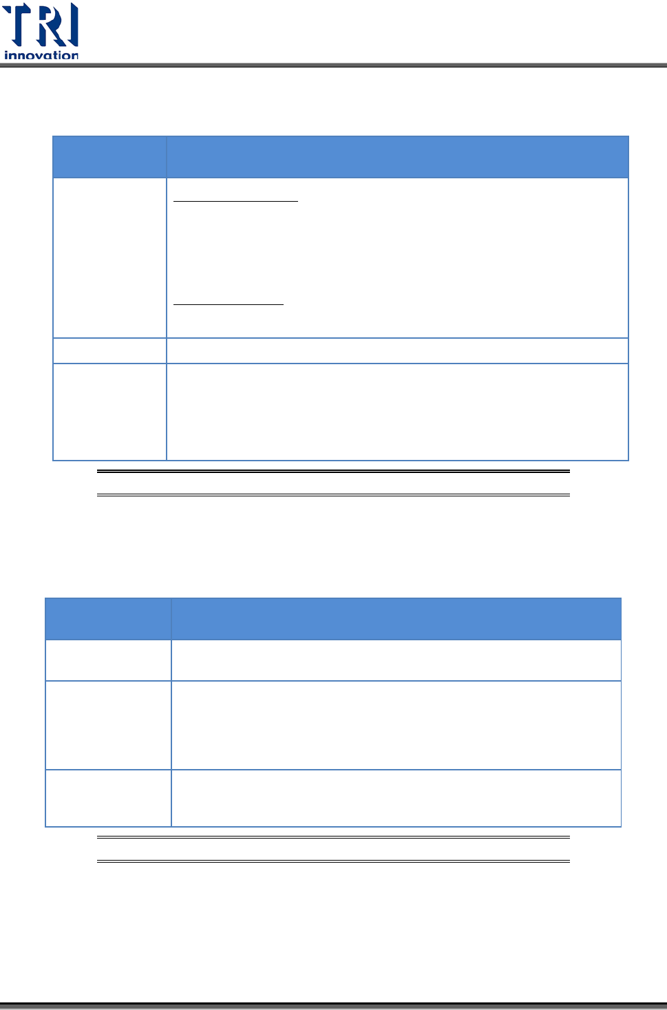
Initialize/Test Switch
SWITCH
POSITION
OPERATION MODE
INITIALIZE
(upward)
In the PROG. mode:
The contents of the operation memory are initialized. However, the
system register (including the I/O map) and the program are not
initialized. If the error of self-diagnostic error code 42 or lower is
occurred, the special internal relays R9000 to R9008 and the special
data register DT90000 are not cleared.
In the RUN mode:
Operation errors, remote I/O system errors, and battery errors are
cleared.
(center)
The switch should normally be left in this position.
TEST
(downward)
Setting this switch to the downward position in the PROG. mode,
accesses the TEST mode. Switching to the RUN mode in this status,
initiates test operation.
To return from the TEST mode to normal operation, return this switch to
the center position in the PROG. mode.
圖
80: CPU(FP2-C1)
單元
–Initialize/Test Switch
Mode Selector
SELECTOR
POSITION
OPERATION MODE
RUN (upward)
This sets the RUN mode. The program is executed, and operation
begins.
REMOTE (center)
This enables operation to be started and stopped from a programming
tool. At the stage where the selector is changed, when switching from
the PROG. to the REMOTE mode, the system remains in the PROG.
mode and when switching from RUN mode to the REMOTE mode, it
remains in the RUN mode.
PROG.
(downward)
This sets the PROG. mode. In this mode, programming can be done
using tools, the test operation mode can be accessed and the
operation memory can be initialized using the initialize/test switch.
圖
81: CPU(FP2-C1)
單元
–Mode Selector
3.6.2
四軸控制器
(FP2-PP4)
單元
Operation Status Display LEDs