TR7007SII_Hardware_ch-v1-0-1 - 第47页
Test Research Inc. TR 7007 SII User Guide – Hardwa re 35 LED Descripti on LED On LED Off A Pulse out put sign al A Blinking d uring p ulse output During s top B Pulse out put sign al B Reverse dir ection comm and Forward…
Test Research Inc.
34 TR7007 SII User Guide – Hardware
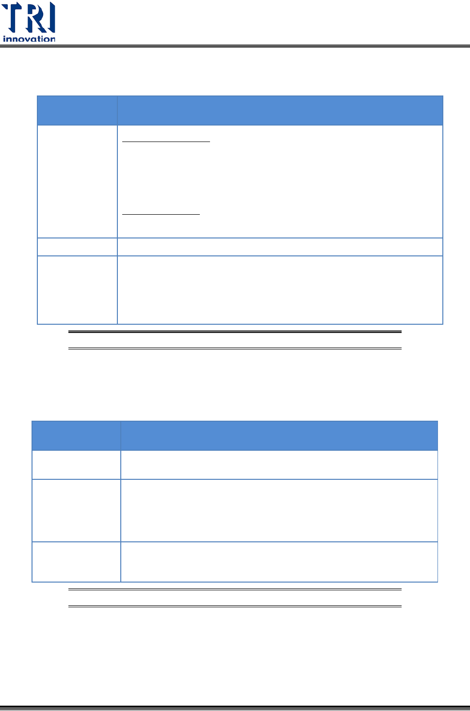
Initialize/Test Switch
SWITCH
POSITION
OPERATION MODE
INITIALIZE
(upward)
In the PROG. mode:
The contents of the operation memory are initialized. However, the
system register (including the I/O map) and the program are not
initialized. If the error of self-diagnostic error code 42 or lower is
occurred, the special internal relays R9000 to R9008 and the special
data register DT90000 are not cleared.
In the RUN mode:
Operation errors, remote I/O system errors, and battery errors are
cleared.
(center)
The switch should normally be left in this position.
TEST
(downward)
Setting this switch to the downward position in the PROG. mode,
accesses the TEST mode. Switching to the RUN mode in this status,
initiates test operation.
To return from the TEST mode to normal operation, return this switch to
the center position in the PROG. mode.
圖
80: CPU(FP2-C1)
單元
–Initialize/Test Switch
Mode Selector
SELECTOR
POSITION
OPERATION MODE
RUN (upward)
This sets the RUN mode. The program is executed, and operation
begins.
REMOTE (center)
This enables operation to be started and stopped from a programming
tool. At the stage where the selector is changed, when switching from
the PROG. to the REMOTE mode, the system remains in the PROG.
mode and when switching from RUN mode to the REMOTE mode, it
remains in the RUN mode.
PROG.
(downward)
This sets the PROG. mode. In this mode, programming can be done
using tools, the test operation mode can be accessed and the
operation memory can be initialized using the initialize/test switch.
圖
81: CPU(FP2-C1)
單元
–Mode Selector
3.6.2
四軸控制器
(FP2-PP4)
單元
Operation Status Display LEDs
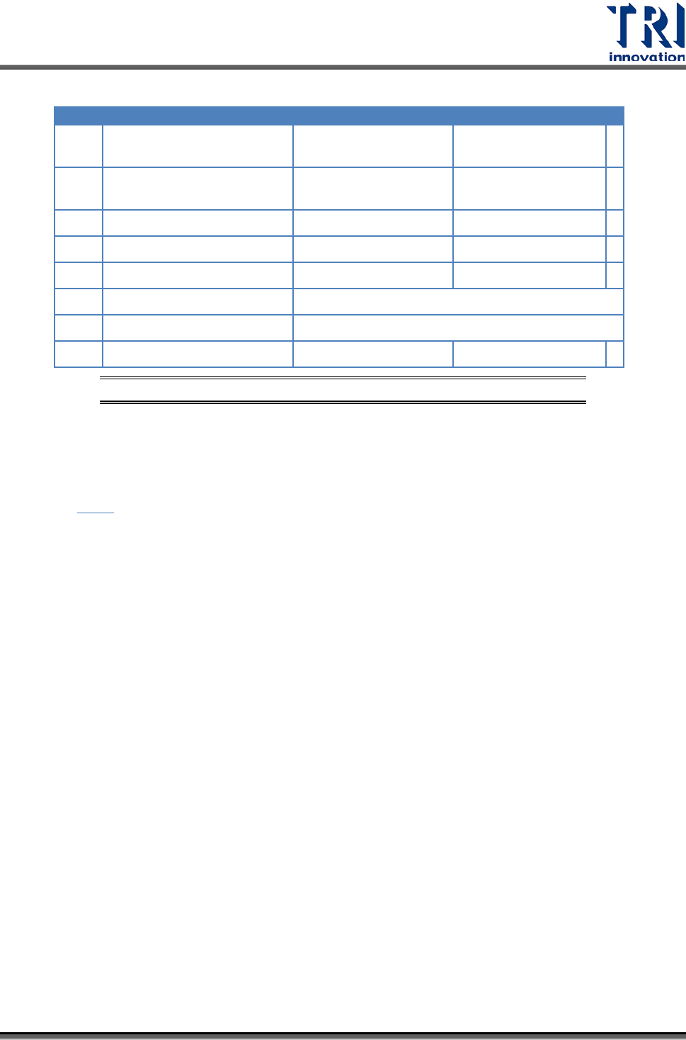
Test Research Inc.
TR7007 SII User Guide – Hardware 35
LED
Description
LED On
LED Off
A Pulse output signal A
Blinking during pulse
output
During stop
B Pulse output signal B
Reverse direction
command
Forward direction
command
CL
Counter clear signal output
Output: on
Output: off
D
Near home status
On
Off
Z
Home input status
On
Off
PA
Pulser signal input
Display input status of pulser input signal A
PB
Pulser signal input
Display input status of pulser input signal B
ERR
Setting value error
Setting value: error
Setting value: normal
圖
82:
四軸控制器
(FP2-PP4)
單元
–Operation Status Display LEDs
3.6.3 I/O (FP2-XY64D2T & FP2-Y16P)
單元
請參考
圖
56。
Test Research Inc.
36 TR7007 SII User Guide – Hardware
4
輸送帶
4.1
架構及功能
輸送帶主要功能在於帶動 PCB 完成進出板的動作,在機台長期運行之下,可能因人為
因素造成輸送帶未完全落於從動軸上,建議使用者在使用機台時,能注意前後輸送帶
是否落於從動軸上,可增加輸送帶的使用壽命;若需更換皮帶,則將皮帶套在兩側的
從動軸上後,再依序套入內側的從動軸上即可。
4.2
感應器
(Sensor)
調整及更換
1) 感應器 1 及感應器 4 (進出板用感應器):用調棒調整感應器強度至指示燈亮(感應
器上方有遮蔽物時,其指示燈會亮,若感應器上方無遮蔽物,則指示燈熄滅),再
慢慢減弱至指示燈熄滅,即為進出板之最佳感測狀態。
2) 感應器 2 及感應器 3 (減速及停板感應器):調整方式同上。
3) 感應器 5 及感應器 6 (夾板馬達感應器) 。
4) 更換:若感應器無動作,需先重新調整感應器靈敏度,若仍然無動作,不需維
修,直接更換新的感應器;更換方法:先將感應器接頭卸下,再將感應器本體卸
下,然後將新的感應器裝上,最後再將感應器接頭裝上並鎖緊,更換完畢後,再
依調整方法重新調整。
4.3
前後站連線
4.3.1
前站連接方式
PORT1=UP LINE :Y104-Black(1) / Green (2) ->Ready
:X8A-Red(3) / Blue(4) ---------->Board available
:X8B-Yellow (5)/ White(6) ->Spare
於設備後方電源插座之下方,有一 I/O PORT1,接上連接線,線頭部分共有三組不同
顏色的兩條線之接頭,分別為黑綠(Y104)向前站要板訊號,紅藍(X8A)預留之 INPUT
接頭,黃白(X8B)預留之 INPUT 接頭。將黑綠接頭與前站接受要板訊號之接頭相結合
即可。(我們為標準 SMEMA 訊號,若各廠家有不相同,在連線時,可與前站廠家聯
繫,取得連線資料)