80S-2080F480F5.pdf - 第185页
SIPLACE 80S-20/F4/F5 User M anual 4 Single Functions 05/99 Issue from Software Version SR.405.xx 4.2 Single Functions, Gantry with 12x Revolver Head 4 - 9 4.2.2. 2 S t ar step This fun ction is used for ad vancing the st…
4 Single Functions SIPLACE 80S-20/F4/F5 User Manual
4.2 Single Functions, Gantry with 12x Revolver Head 05/99 Issue from Software Version SR.405.xx
4 - 8
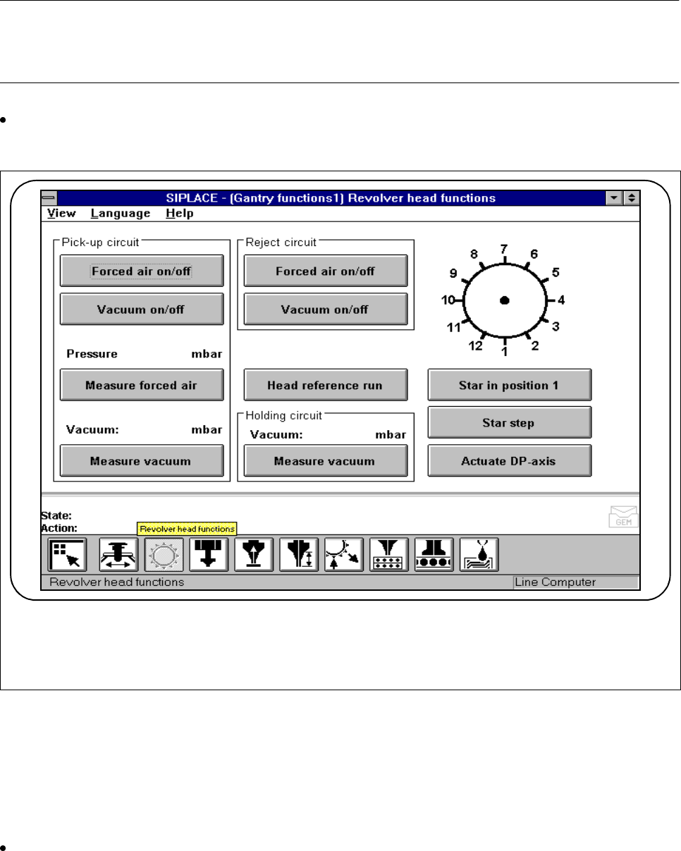
4.2.2 Revolver Head Functions, 12x Revolver Head
In the
Revolver head functions
menu you can control revolver head functions.
NOTE
When the cover is open the revolver head functions can be carried out only when the key-operated switch has
been turned.
In the
Gantry functions
menu, click on the symbol button for
Revolver head functions.
The current position of the star will be shown each time.
Fig. 4.2.3 Revolver head functions, 12x revolver head
4.2.2.1 Star in Position 1
This function is used for bringing the star into a defined starting position. To this end the star and the z axis
perform a reference run.
Click on the Star in position 1 button. The star will then be moved until the segment of star position 1 is in
the pick-up and placement position (the lowest position).
F

SIPLACE 80S-20/F4/F5 User Manual 4 Single Functions
05/99 Issue from Software Version SR.405.xx 4.2 Single Functions, Gantry with 12x Revolver Head
4 - 9
4.2.2.2 Star step
This function is used for advancing the star one position at a time.
Click on the
Step
button. The star will be advanced by one segment. Each time you click the star will be
moved forward by one segment. The current position of the star is shown in the diagram.
4.2.2.3 Actuate DP Axis
When this function is activated the nozzle in the dp1 axis is rotated by 90
o
.
Click on the
Actuate dp axis
button. The nozzle in the dp1 axis will be rotated by 90
o
once.
4.2.2.4 Pick-Up Circuit - Forced Air On / Off
When this function is activated, the forced air at the pick-up position will be switched on or off.
Within the
Pick-up circuit
working area click on the
Forced air on / off
button. At the nozzle which is in
the pick-up position the forced air will be switched on or off.
4.2.2.5 Pick-Up Circuit- Measure Forced Air
When this function is activated, the activated forced air at the pick-up position will be measured.
Switch the forced air on.
Within the
Pick-up circuit
working area click on the
Measure forced air
button. At the nozzle which is in
the pick-up position the forced air will be measured. The results of measurement will be shown in the dis-
play window.
PLEASE NOTE
The values shown in the window do not correspond to the actual values at the nozzle.
When the settings are made, the values are determined using a manometer (see Adjustment instructions
or the Service Manual).
Switch the forced air off.
4.2.2.6 Pick-Up Circuit - Vacuum On / Off
When this function is activated, the vacuum at the pick-up position will be switched on or off.
Within the Pick-up circuit working area click on the Vacuum on / off button. At the nozzle which is in the
pick-up position the vacuum will be switched on or off.

4 Single Functions SIPLACE 80S-20/F4/F5 User Manual
4.2 Single Functions, Gantry with 12x Revolver Head 05/99 Issue from Software Version SR.405.xx
4 - 10
4.2.2.7 Pick-Up Circuit - Measure Vacuum
When this function is activated, the activated vacuum at the pick-up position will be measured.
Switch the vacuum on.
Within the
Pick-up circuit
working area click on the
Measure vacuum
button. At the nozzle which is in the
pick-up position the vacuum will be measured. The results of measurement will be shown in the display
window.
Switch the vacuum off.
4.2.2.8 Reject Circuit - Forced Air
When this function is activated, the forced air at the reject position will be switched on.
Within the
Reject circuit
working area click on the
Forced air
button. At the nozzle which is in the pick-up
position the forced air will be switched on.
4.2.2.9 Reject Circuit - Vacuum
When this function is activated the vacuum at the reject position will be switched on.
Within the
Reject circuit
working area click on the
Vacuum
button. At the nozzle which is in the reject
position the vacuum will be switched on.
4.2.2.10 Head Reference Run
When this function is activated the head axes will carry out a reference run. During this run gantry axes x and
y will travel over the reject container in order to discard components in a defined manner.
Within the working area click on the
Head reference run
button. The head axes will perform a reference
run.
4.2.2.11 Holding Circuit - Measure Vacuum
When this function is activated, the vacuum in the holding circuit will be measured.
Within the
Holding circuit
working area click on the
Measure vacuum
button. The vacuum is measured
at the nozzle which is in the holding circuit.