80S-2080F480F5.pdf - 第236页
5 Vision Functions SIP LACE 80S-20/F4/F5 Us er Manual 5.1 Overview of the Vision Systems i n the SIPLACE 80S-20/F4F5 Machines 05/99 Issue from Software Version SR.405.xx 5 - 4 Line en gineer
SIPLACE 80S-20/F4/F5 User Manual 5 Vision Functions
05/99 Issue from Software Version SR.405.xx 5.1 Overview of the Vision Systems in the SIPLACE 80S-20/F4F5 Machines
Line engineer 5 - 3
5.1 Overview of the Vision Systems in the
SIPLACE 80S-20/F
4
F
5
Machines
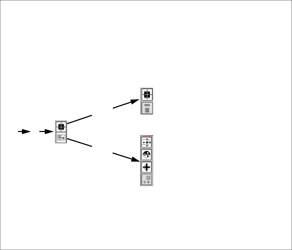
Fig. 5.1.1 Overview
Test component
Select package form and camera type
Test and center fiducial,
position gantry, PCB transport functions
Set contrast sensitivity
Teach fiducial and
determine search field size and resolution
Select fiducial and gantry
From flow chart 2.3.2
Vision functions
Teach and test
PCB fiducials
Measure component and
modify package form data
5 Vision Functions SIPLACE 80S-20/F4/F5 User Manual
5.1 Overview of the Vision Systems in the SIPLACE 80S-20/F4F5 Machines 05/99 Issue from Software Version SR.405.xx
5 - 4 Line engineer
SIPLACE 80S-20/F4/F5 User Manual 5 Vision Functions
05/99 Issue from Software Version SR.405.xx 5.1 Overview of the Vision Systems in the SIPLACE 80S-20/F4F5 Machines
Line engineer 5 - 5
As the dimensions of components become smaller and smaller in size, the lead interconnection and insertion
densities increase, and board structures become more complex, the quality demands on the placement accu-
racy of the machines continue to rise. In order that these requirements be satisfied the SIPLACE 80 S-20/
F
4
placement machines are equipped with optical recognition systems (so-called
vision systems
) not only for
centering the printed circuit boards (
PCB vision system
) but also for centering the components (
component
vision system
).
5.1.1 Vision Systems in the SIPLACE 80S-20 Placement Machine
On the SIPLACE 80S-20 automatic placement machine, with its double gantry system and two 12x revolver
placement heads, each placement head is equipped with a CCD camera system for component position rec-
ognition. In addition a CCD camera system for PCB position recognition is mounted on each gantry underside
(5 - 5 and Fig. 5.1.3, Page 5 - 6).
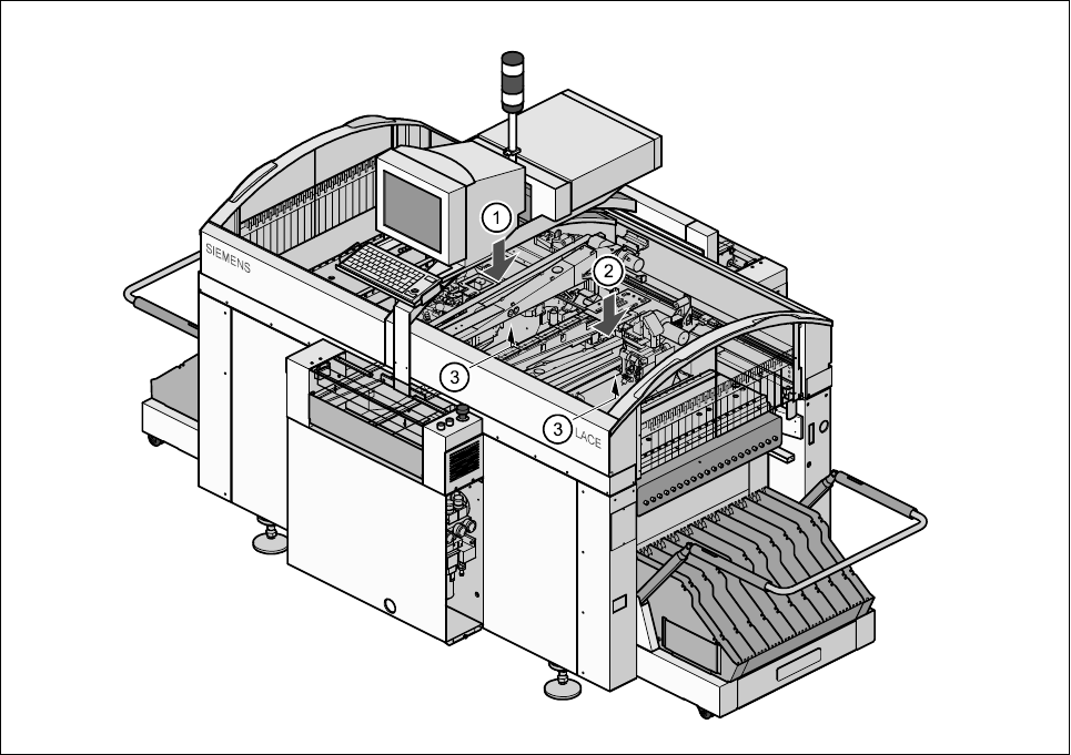
Fig. 5.1.2 Location of the 12x revolver placement heads on the SIPLACE 80S-20 placement machine
- Key to Fig. 5.1.2
1 12x placement head / gantry 1 2 12x placement head / gantry 2
3 PCB cameras under the gantries
The range of components which can be handled by optical centering and placement ranges from 0402 to
SO28 components, or, to put it another way, component sizes varying between 1.0 mm x 0.5 mm up to a max-
imum of 18.7 mm x 18.7 mm with component thicknesses from 0.3 mm to 8.25 mm.
The PCB vision system of the 80S-20, 80F
4
and 80F
5
machines centers boards with dimensions ranging from
a minimum of 50 mm x 50 mm up to 460 mm x 460 mm (standard), with an optional maximum of 508 mm x
460 mm. The board thickness may vary within the range of 0.5 mm and 4.5 mm.