80S-2080F480F5.pdf - 第242页
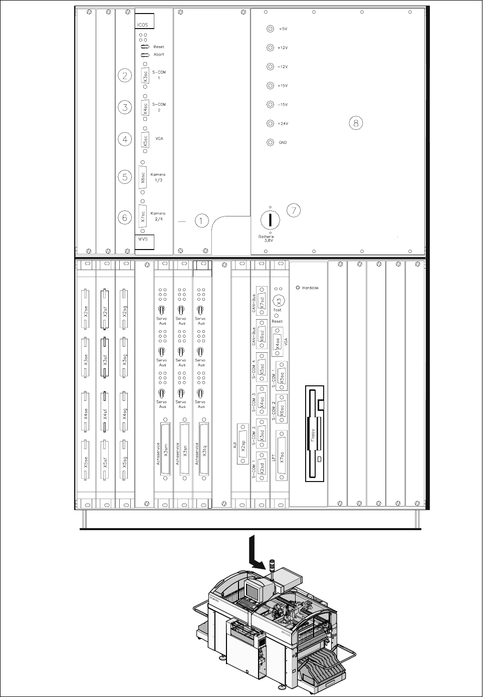
5 Vision Functions SIP LACE 80S-20/F4/F5 Us er Manual 5.1 Overview of the Vision Systems i n the SIPLACE 80S-20/F4F5 Machines 05/99 Issue from Software Version SR.405.xx 5 - 10 Line en gineer Fig. 5.1.7 Vision evaluation…
SIPLACE 80S-20/F4/F5 User Manual 5 Vision Functions
05/99 Issue from Software Version SR.405.xx 5.1 Overview of the Vision Systems in the SIPLACE 80S-20/F4F5 Machines
Line engineer 5 - 9
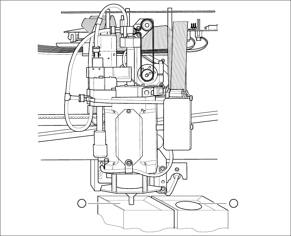
Fig. 5.1.6 Location of the component camera system for the IC placement head
- Key to Fig. 5.1.6
1 IC sensor system 2 FC (flip chip) sensor system
The evaluation unit (ICOS MVS system) which is accommodated in the machine’s control unit (5 - 10) pro-
cesses and evaluates the signals from the PCB and component camera systems of the 12x revolver and IC
placement heads. The deviations from the nominal values are used for determining correction values which
are then used in the recalculation of the placement positions and the skew of the components to be inserted.
- Key to Fig. 5.1.7
1 PCB and component evaluation unit of vision system 2 COM1
3 COM2 4 Screen connection
5 Camera connections 6 Camera connections
1 PCB camera 2 IC-head camera
3 Component camera, 12x revolver head 4 FC camera
7 Battery 8 Power supply unit
1 2
5 Vision Functions SIPLACE 80S-20/F4/F5 User Manual
5.1 Overview of the Vision Systems in the SIPLACE 80S-20/F4F5 Machines 05/99 Issue from Software Version SR.405.xx
5 - 10 Line engineer
Fig. 5.1.7 Vision evaluation unit in the SIPLACE 80F
4
placement machine
SIPLACE 80S-20/F4/F5 User Manual 5 Vision Functions
05/99 Issue from Software Version SR.405.xx 5.1 Overview of the Vision Systems in the SIPLACE 80S-20/F4F5 Machines
Line engineer 5 - 11
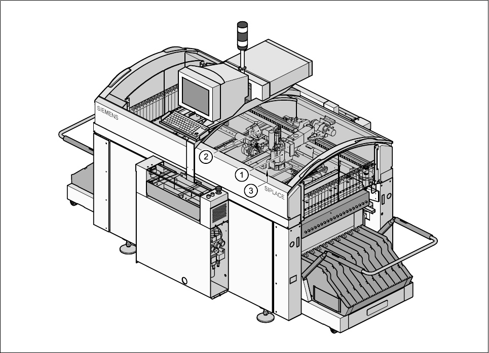
5.1.3 Vision Systems in the SIPLACE 80F
5
Placement Machine
The single gantry system of the SIPLACE 80F
5
machine (see Fig. 5.1.8) is fitted with one 6x revolver place-
ment head and one IC placement head. The revolver placement head is equipped with a camera system for
component position recognition (5 - 12). The camera systems (up to two) for component position recognition
at the IC head are mounted on the machine base (5 - 9).
Fig. 5.1.8 Position of the placement heads and of the PCB vision system on the SIPLACE 80F
5
placement machine
- Key to Fig. 5.1.8
1 IC placement head 2 6x revolver placement head
3 PCB camera on the underside of the gantry
Range of components in relation to the placement head and vision system
The following components can be optically centered using the component vision systems and placement
heads developed for the 80F
5
automatic placement systems:
–
6-nozzle revolver head with standard component vision system (5 - 12)
The 6-nozzle revolver head and a standard component vision system can be used to optically center and
insert standard components up to 32mm x 32mm.
–
6-nozzle revolver head with component vision system for flip-chips, bare dies and standard components
(DCA option) (5 - 14)
The 6-nozzle revolver head and a component vision system for flip-chip components, bare dies and stan-
dard components can be used to optically center and insert components up to 13mm x 13mm.
–
IC head
The IC head and IC vision system can be used to visually center and insert components up to 55mm x
55mm in size. The FC vision system can be used to visually center components up to 20 mm x 20 mm (5 -
9).