80S-2080F480F5.pdf - 第300页
5 Vision Functions SIP LACE 80S-20/F4/F5 Us er Manual 5.5 Teach Fiducial 05/99 Issue from Software Version SR.405.xx 5 - 68 Line en gineer 5.5.6 .3 Move X/ Y Ax es Option When yo u sele ct this opt ion fro m the T est fi…
SIPLACE 80S-20/F4/F5 User Manual 5 Vision Functions
05/99 Issue from Software Version SR.405.xx 5.5 Teach Fiducial
Line engineer 5 - 67
5.5.6.2
Test
Option
If you click on the
Test
button the
Test fiducial
menu will close and the video image be displayed on the
screen.
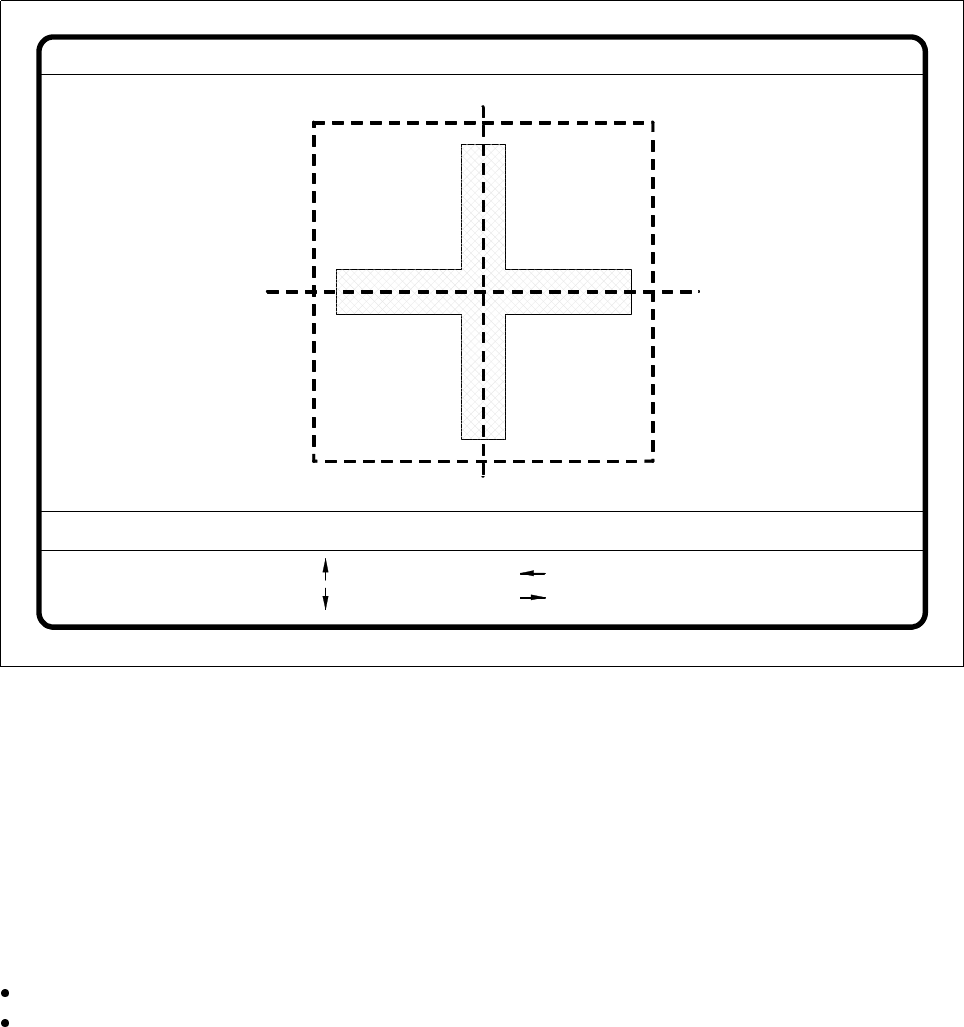
Fig. 5.5.25
Test fiducial
menu,
Test
video image
The dimensions of the pattern structure and search area are stored in the station computer. These figures are
required for calculating the travel path for the corners test. The centering offsets of any fiducial centering
which may already have been carried out will also be taken into account in calculating the travel path. Follow-
ing this
– the test will be shown in the video image as it runs,
– the header will be shown with the option, the fiducial number and the quality factor, and
– in the footer the operator fields and command sequences will be shown and a test started which deter-
mines the fiducial’s quality factor.
By pressing the Return key you can repeat the test procedure.
You can change the position of the gantry with the arrow keys. By entering the numbers 1 - 6 you can
change the step width.
The PCB camera travels into the 4 corners of the search area and each time issues a measurement com-
mand. For each measurement command the machine controller is provided with the fiducial quality by the
vision evaluation unit (MVS). The worst value (which is the worst case) of the test is displayed on the screen
in the header.
The quality value will be a figure between 0 (= bad) and 100 (= very good) and should not fall below the value
40 for the fiducial and the ink dot. If it does, we recommend you choose another fiducial.
Fiducial No. = 8 Quality fact. = 70Test fiducial
test
1..6 : x/y step
Ret :
x/y step width = ...
: x axis +
: x axis -
: y axis +
: y axis -
5 Vision Functions SIPLACE 80S-20/F4/F5 User Manual
5.5 Teach Fiducial 05/99 Issue from Software Version SR.405.xx
5 - 68 Line engineer
5.5.6.3
Move X/ Y Axes
Option
When you select this option from the
Test fiducial
menu, the station computer will have the following actions
carried out:
– The screen will close the
Test fiducial
menu and will switch over to the video image. At the same time the
current camera position will be displayed and the operator field option dropped down.
– If there is the risk of a crash the axis controllers will be blocked.
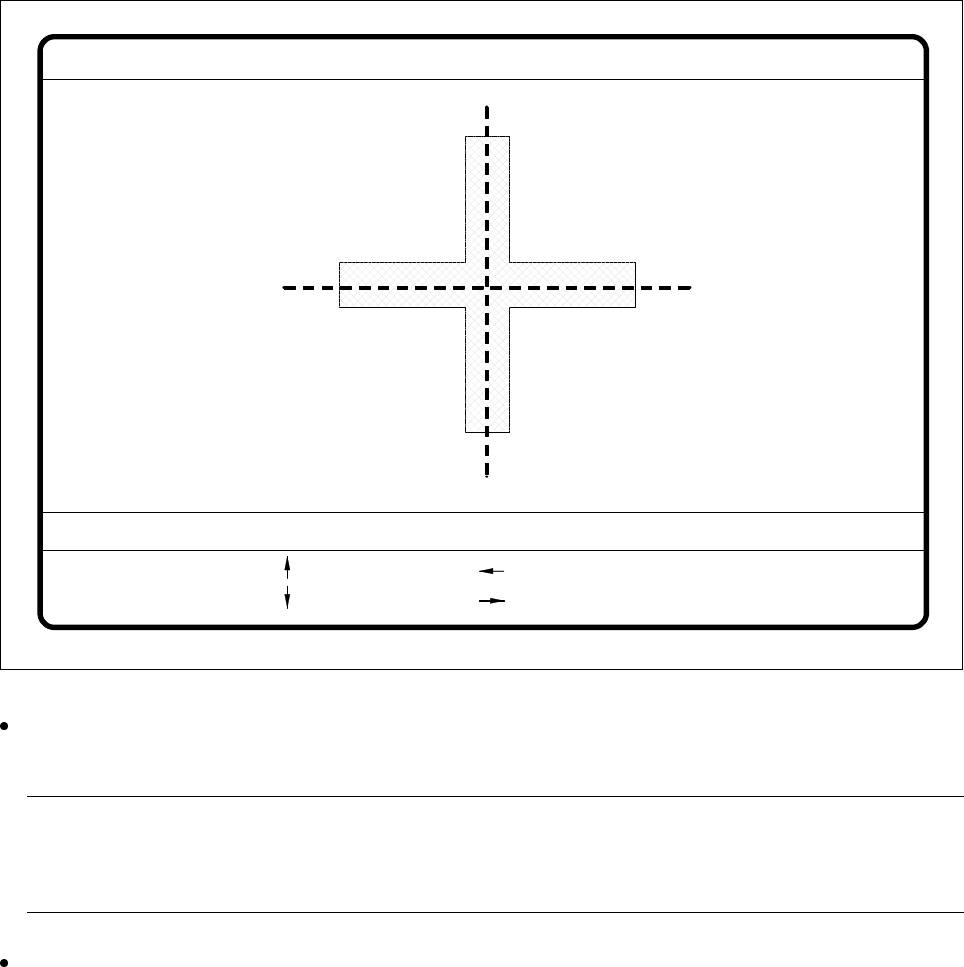
Fig. 5.5.26
Test fiducial
menu,
Move x/y axes
video image
After selecting the step width (by choosing a number between 1 and 6) you can use the arrow keys to
change the camera position of gantry 1.
NOTE
The default teaching gantry is always Gantry 1. You can however select Gantry 2 for this by using the
Select gantry option (see Section 5.5.3.1, Page 5 - 46).
With Esc you can quit the option. The Test fiducial menu will be displayed again.
: x axis +
: x axis -
: y axis +
: y axis -
1..6: x/y step
x pos. cam = y pos. cam =
Move x/y axes
x/y step width =

SIPLACE 80S-20/F4/F5 User Manual 5 Vision Functions
05/99 Issue from Software Version SR.405.xx 5.5 Teach Fiducial
Line engineer 5 - 69
5.5.6.4
PCB onto Center Conveyor
Option
Click on the
PCB to center conveyor
button and the following actions will be executed:
1. There is a board on the input conveyor.
– The conveyor belt starts and conveys the board as far as the stopper.
– The board will be clamped.
2. There is no board on the input conveyor.
– The message appears: ’No PCB on the input conveyor’.
– Insert a board.
– Click on the
PCB to center conveyor
button.
– The conveyor belt starts and conveys the board as far as the stopper.
– The board will be clamped.
NOTE
If there is already a board on the center conveyor, this function will be blocked. You will then see a mes-
sage informing you that there is already a board on the center conveyor.
NOTE
If a twin conveyor is installed you can use the buttons in the option box ’Conv. selection’ to select con-
veyor 1 or conveyor 2.
5.5.6.5
PCB to Output Conveyor
Option
This function will only be executed when there is a board on the center conveyor.
NOTE
When you quit the menu the board will be transported automatically onto the output conveyor.
NOTE
If a twin conveyor is installed you can use the buttons in the option box ’Conv. selection’ to select conveyor 1
or conveyor 2.