80S-2080F480F5.pdf - 第312页
5 Vision Functions SIP LACE 80S-20/F4/F5 Us er Manual 5.6 Test Component 05/99 Issue from Software V ersion SR.405.xx 5 - 80 Line en gineer Fig. 5.6.8 Flowchart ’T est componen t’, LEAD, GRID, and BALL measure mode menus…
SIPLACE 80S-20/F4/F5 User Manual 5 Vision Functions
05/99 Issue from Software Version SR.405.xx 5.6 Test Component
Line engineer 5 - 79
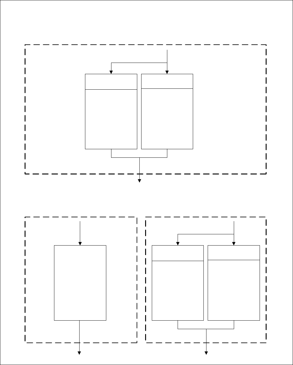
Fig. 5.6.7 Flowchart ’Test component’, ROW and CORNER’ measure mode menus
’Test component’ menu options
’ROW measure mode’ and ’CORNER measure mode’ menus
’ROW measure mode’ menu
’CORNER measure mode’ menu
Tip measurement
via inner tips
Center
measurement
Tip measurement
via outer tips
Measurement
No. of pins to be measured
at each corner
One window
across the whole
lead window
No. of pins
at each corner
Cancel Accept
Angle measurement
activated
Yes/No
low
medium
high
very high
Resolution in
meas. direction
Resolution in
direction of
integration
low
medium
high
very high
Tip measurement
via inner tips
Center
measurement
Tip measurement
via outer tips
Measurement
Use package
form edges
For the
rotational
windows
For the
translational
windows
Cancel Accept
Cancel Accept
’ROW measure mode’ menu -
integration settings
5 Vision Functions SIPLACE 80S-20/F4/F5 User Manual
5.6 Test Component 05/99 Issue from Software Version SR.405.xx
5 - 80 Line engineer
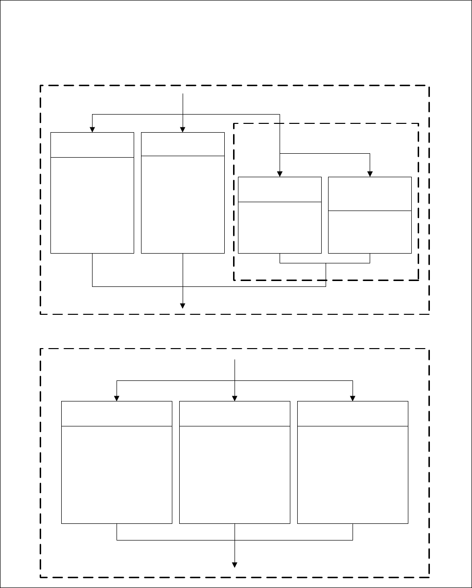
Fig. 5.6.8 Flowchart ’Test component’, LEAD, GRID, and BALL measure mode menus
’Test component’ menu options
’LEAD’, ’GRID’, and ’BALL’ measure mode menus
’LEAD measure mode’ menu ’
Tip measurement
via inner tips
Center
measurement
Tip measurement
via outer tips
Measurement Window
Separately
for each pin
Combined
windows
Cancel Accept
Number of
balls to be
measured
Cancel Accept
Fast
Robust
Measurement Evaluation
Position
and
existance
Quality
Cancel Accept
’GRID measure mode’ menu ’BALL measure mode’ menu
SIPLACE 80S-20/F4/F5 User Manual 5 Vision Functions
05/99 Issue from Software Version SR.405.xx 5.6 Test Component
Line engineer 5 - 81
5.6.3
Select Package Form
Menu
If you select the
Test component
option in the
Main view
menu this will launch the following actions:
The functions for the vision system are activated in the station computer
The
Select package form
menu will drop down.
The station computer will determine the package form numbers list with commentaries from the set-up.
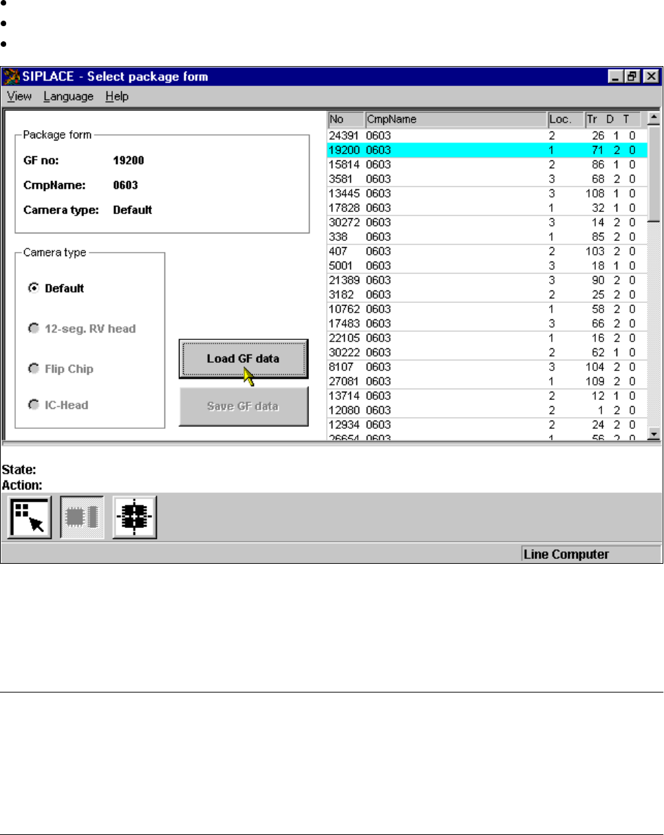
Fig. 5.6.9
Select package form
menu
The menu allows you to choose between the following options, as the diagram shows:
– Selection of the camera types (80F
4
or 80F
5
machines only, see Section 5.10, Page 5 - 163).
– Load GF data
– Save GF data
NOTE
Buttons are active when the text on the button is black (rather than gray). This means that you can launch the
associated function by clicking on the button with the mouse.
The Load GF data button will, for example, only be active if you have previously clicked on a package form in
the lists field.
The Save GF data button will only be active if you have changed the package form parameters.